KE2010.Instruction Manual.Ver.2.01,Rev.08.pdf - 第1355页
272 8 12 5 ELGNum Pos The s ystem f ailed t o det ect som e balls on a c omponent . − The bal l pitc h or diam eter is not entered corr ectly . − Thi s error occ urs als o when there is a subst ance that reflect s light …
271
10. Detailed Explanation of the Recognition Errors of General-Purpose Vision
Components (LeaBalld Components/Outline-Recognized Components)
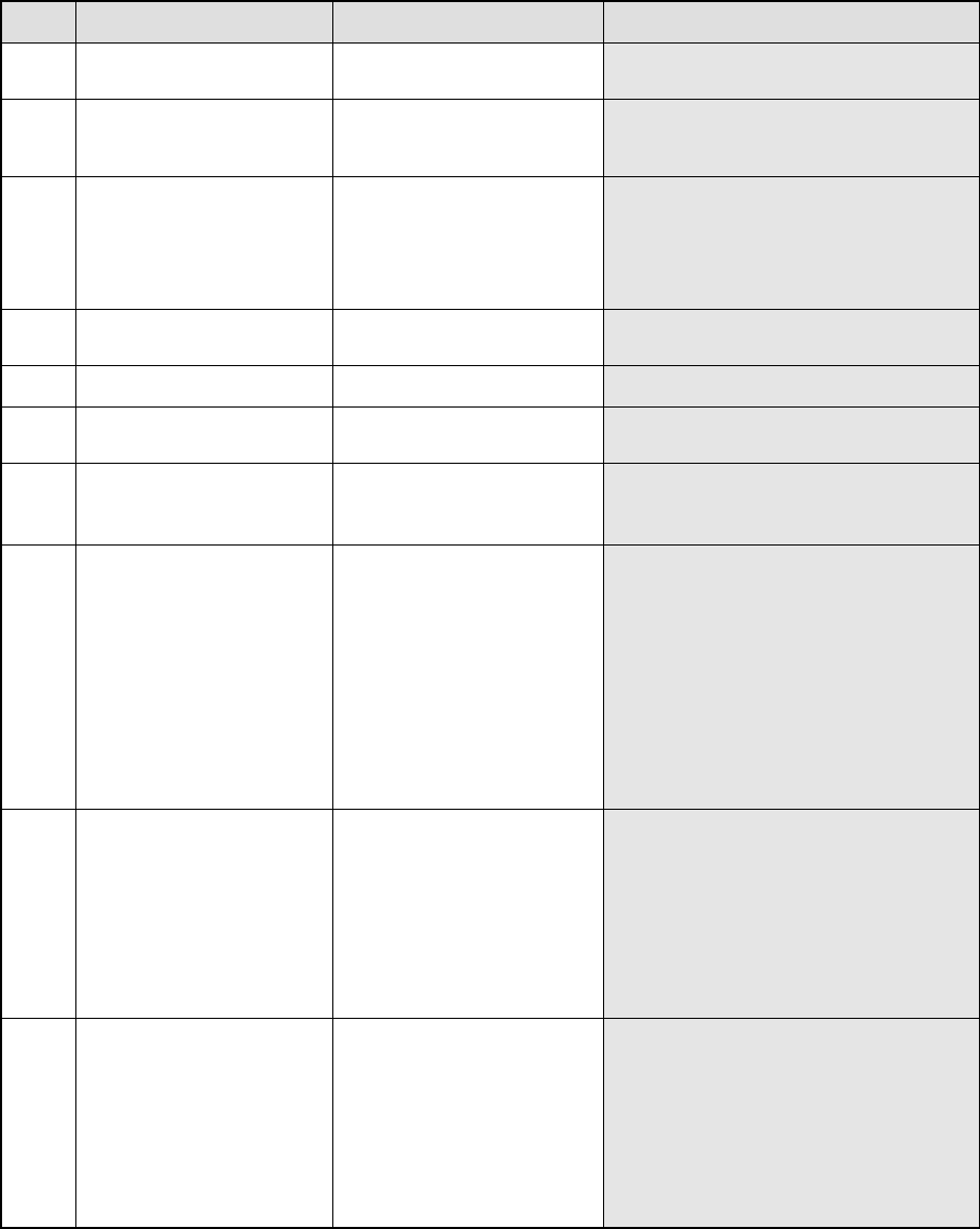
‘RES M N RDM_BALL Index ErrCode …..’
M: Number of components recognized at the same time
N: Phase number for simultaneous component recognition
Index: Component identification number
Err
Code
Description of an error Assumed cause
7 ELGNum Pos Pitch The ball pitch is abnormal
− The ball coordinates are not specified
correctly.
(when an expansion array is used)
8 6 ELGNum Pos S ErrLv The ball area error occurs.
− This error occurs when a ball is chipped.
− This error occurs also when a ball(s) is
(are) not displayed clearly due to its
(their) stains or oxidation.
8 7 ELGNum Pos D ErrLv The ball diameter error occurs.
− This error occurs when a ball is chipped.
− This error occurs also when a ball is
deformed entirely.
(“*” is displayed at Pos.)
− This error occurs also when the actual
ball diameter is quite different from that
you set. (“*” is displayed at Pos.)
8 9 En ELGNum Pos Dia There is no ball on a component.
− This error occurs when the ball diameter
is very abnormal because a ball is
chipped or due to a bridge.
8 10 En ELGNum Pos V
Vth
There is no ball (ball brightness
error)
− The tip of a ball is chipped.
8 11 The sampled balls are too few.
− The system detects only two or less balls
correctly due to stains or oxidation of
balls.
8 12 0 The system failed to position a
component.
− The ball assignment setting is not
correct.
− A wrong ball diameter is entered.
− The hardware malfunctions.
8 12 0 RC1 504 RC2 The system failed to detect any
ball.
− This error occurs due to a wrong
component type.
− This error occurs also when a
component is not picked up.
− This error occurs also when a ball(s) is
(are) not displayed clearly due to its
(their) stains or oxidation.
− This error occurs also when the light
does not turn on.
− This error occurs also when contrast
between a ball and its background is low.
− This error occurs also when there are
many balls and many substances similar
with a ball on a component.
8 12 0 RC1 508 RC2 The system failed to position a
component.
− The ball assignment setting is not
correct.
− A wrong ball diameter is entered.
− This error occurs also when a ball(s) is
(are) not displayed clearly due to its
(their) stains or oxidation.
− This error occurs also when contrast
between a ball and its background is low.
− This error occurs when there are many
marks or other substances similar with a
ball on a component.
8 12 0 RC1 510 RC2 Time-out error (It takes four
seconds or more for the system
to recognize a component, then
the system interrupts recognition
of the component. This error
occurs at the VCS whose
version is 1.11AF or later.)
− The ball assignment setting is not
correct.
− A wrong ball diameter is entered.
− This error occurs also when a ball(s) is
(are) not displayed clearly due to its
(their) stains or oxidation.
− This error occurs also when contrast
between a ball and its background is low.
− This error occurs when there are many
balls and marks or other substances
similar with a ball on a component.
272
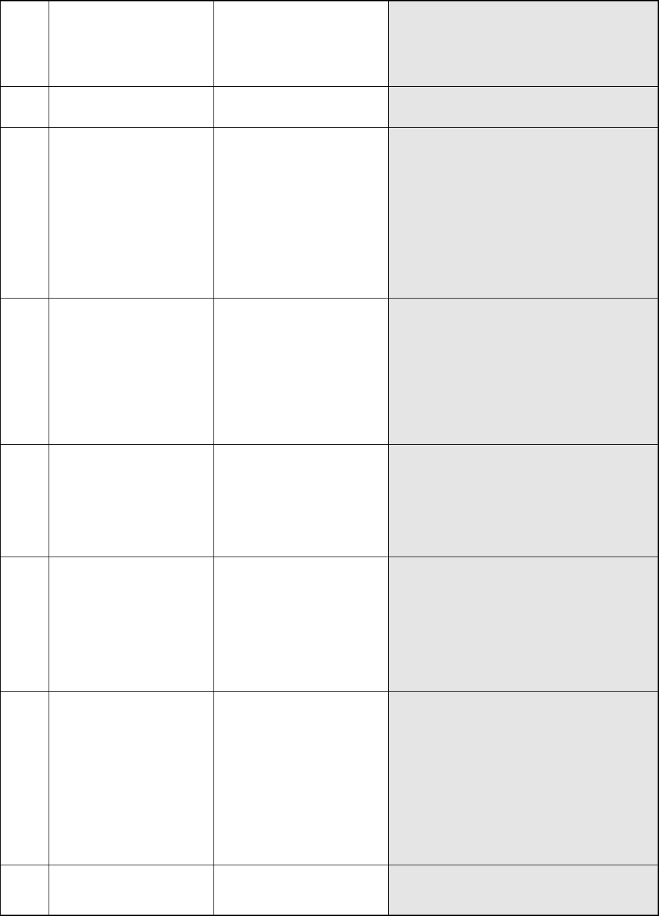
8 12 5 ELGNum Pos The system failed to detect
some balls on a component.
− The ball pitch or diameter is not entered
correctly.
− This error occurs also when there is a
substance that reflects light easily such as a
mark around the perimeter of the package.
− The system has not performed calibration
(setting of the pixel rate).
8 13 0 The system failed to position a
component with the division
recognition function.
− The ball assignment setting is not correct.
− The ball diameter is not entered correctly.
− The hardware malfunctions.
8 13 0 RC1 504 RC2 The system failed to detect a
ball with the division recognition
function.
− The error occurs when the component type is
wrong.
− This error occurs when the system does not
pick up a component.
− This error occurs also when a ball(s) is (are)
not displayed clearly due to its (their) stains or
oxidation.
− This error occurs also when the light does not
turn on.
− This error occurs also when contrast between
a ball and its background is low.
− This error occurs when there are many balls or
other substances similar with a ball on a
component.
8 12 0 RC1 508 RC2 The system failed to position a
component with the division
recognition function.
− The ball assignment setting is not correct
− A wrong ball diameter is entered.
− This error occurs also when a ball(s) is (are)
not displayed clearly due to its (their) stains or
oxidation.
− This error occurs also when contrast between
a ball and its background is low.
− This error occurs when there are many marks
or other substances similar with a ball on a
component: there are two or more
similar-shaped balls around the regulated ball,
and such balls are not defined.
8 13 0 RC1 510 RC2 A time-out error is caused with
the division recognition function.
(It takes four seconds or more
for the system to recognize a
component, then the system
interrupts recognition of the
component. This error occurs
at the VCS whose version is
1.11AF or later.)
− The ball assignment setting is not correct.
− A wrong ball diameter is entered.
− This error occurs also when a ball(s) is (are)
not displayed clearly due to its (their) stains or
oxidation.
− This error occurs also when contrast between
a ball and its background is low.
− This error occurs when there are many balls
and marks similar with a ball on a component.
8 14 ELGNum Err1 The system could not detect any
mark on a component.
− This error occurs when the system recognizes
a mark at a place where no mark should be
located.
− This error occurs also when the light does not
turn on.
− This error occurs also when a mark is in
contact with the mark detecting area.
− This error occurs also when a mark is stained
very much.
− This error occurs also when the VCS hardware
malfunctions.
8 15 ELGNum Err2 The system could not detect any
corner.
− There is no component within the window.
− The binary threshold value is inappropriate.
− The straight line displayed on the window is
too short.
− The edge does not indicate a straight line.
− The angle between the crossed two straight
lines is not 90 degrees.
− When the system detected a corner:
± 0.24 rad
− The system recognized the detected straight
line incorrectly.
(because there are two parallel straight lines
located closely on the window, or other
reason.)
8 16 Xd Yd Correction between the divided
views is abnormal.
− The distance between views is not specified
correctly.
− The angle of the view inclination is not
specified correctly.
273
ELGNum: Element group number at which the system detected an error
Pos: Ball number at which the system detected an error (1 to )
Pitch: Ball pitch detected (mm)
S: Area of a ball at which the system detected an error (mm2)
D: Diameter of a ball at which the system detected an error (mm)
ErLv: Error ratio of a ball at which the system detected an error (%)
En: Number of balls at which the system detected an error with its ball existence check
Dia: Diameter of a ball at which the system detected an error first with its ball existence check
V: Luminance of a ball at which the system detected an error first with its ball existence check
Vth: Ball luminance judgment value used with the ball existence check
Rc1: main error code internally processed with VCS
Rc2: Sub error code internally processed with VCS
“Rc1” and “Rc2” indicate the VCS internal recognition block or internal evaluation parameter. These do
not show the direct (physical) cause of an error, but are necessary for analyzing the error. Let us know
these numbers when you contact us.
RES 1 1 RDM_BALL 0 8 12 5 1 10
Description of the error: The system failed to detect the 10
th
ball of the first element group
on a general-purpose vision ball component whose ID is “0”.
11. Detailed Explanation of an Aluminum Electrolytic Capacitor/GaAsFET
Recognition Error
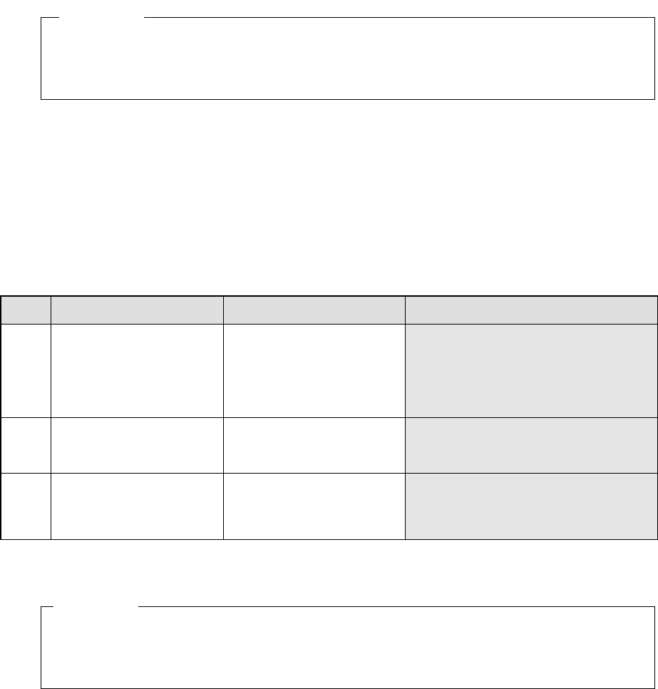
‘RES M N Type Index ErrCode …’
M: Number of components recognized at the same time
N: Phase numbers recognized at the same time
Type: Component type
TER2 (Aluminum electrolytic capacitor), TER4 (GaAsFET)
Index: Component ID number
Err
Code
Description of an error Assumed cause
4 side No lead could be detected.
− An error occurred when the system could
not set the lead detecting window since
the VCS was stained.
− Vision data (lead length) was set
improperly.
* A value ± 30 % of the lead length you
set is judged as a correct length.
7 side Abnormal lead width
− Vision data (lead width) was set
improperly.
* A value ± 20 % of the lead width you
set is judged as a correct width.
12 Abnormal dimensions
− Vision data (dimensions) was set
improperly.
* A value 50 % to 120 % of the
dimension you set is judged as a
correct dimension.
Side: Side on which the system detected an error
(0: Top side 1: Bottom side 2: Left side 3: Right side)
RES 1 1 TER2 0 12
Description of the error: The dimensions of the aluminum electrolytic capacitor whose ID
is “0” are abnormal.
Example
Example