KE2010.Instruction Manual.Ver.2.01,Rev.08.pdf - 第1360页
277 5-3130 The image of a terminal is partially faded. − T his error may occur if the s urface of a terminal does not reflect laser sufficiently . If y ou set the smaller value to the menu item “Electrode Brightness Thre…
276
3-3020 Any shape like a terminal is not found
on the measured image.
(The measurement image is dark.)
− For example, when a component falls
off, and the system tries to measure it
without picking it up, this error occurs.
3-3030 A part of component image lies off the
measurement screen frame.
− A component may slide from the
regulated position during
transportation, so the system cannot
measure it.
− This error may occur also if you enter
the wrong component dimensions.
3-3040 The terminal position is quite different
from that stored as the component
information.
− This error occurs if the component
information indicates a value different
from the actual data.
3-3060 Installation check command
− When your use the gauge block to
adjust the assembling condition with
the MSP parameter, this error may
occur because the gauge block is not
picked up correctly.
6-3110 The component is located closer to the
sensor than regulated with the
measurable range.
− The component height entered may be
different from the actual height of the
component. Check the entered
component height.
FNUM
7-3120 The component is located farther from
the sensor than regulated with
measurable range.
− The component height entered may be
different from the actual height of the
component. Check the entered
component height.
FLIN 4-3070 The measured colinearity value exceeds
the allowable range.
− This is not a system error. Display the
obtained image with a VGA switching
device or check the check box “Stop
system on any error” on the Production
(Pause) tab invoked from the Operation
option dialog box to display the detailed
information and check an error
terminal.
FABS 5-3080 A terminal is missing.
A terminal is bent too much.
The system cannot sample effective
data from terminals (the measured
image of a terminal section is shifted.)
− Display the obtained image with a VGA
switching device or check the check
box “Stop system on any error” on the
Production (Pause) tab invoked from
the Operation option dialog box to
display the detailed information and
check an error terminal.
− If a terminal is bent by1/3 of a lead
pitch or more, or bent by the same
amount as the lead width longitudinally,
this error occurs.
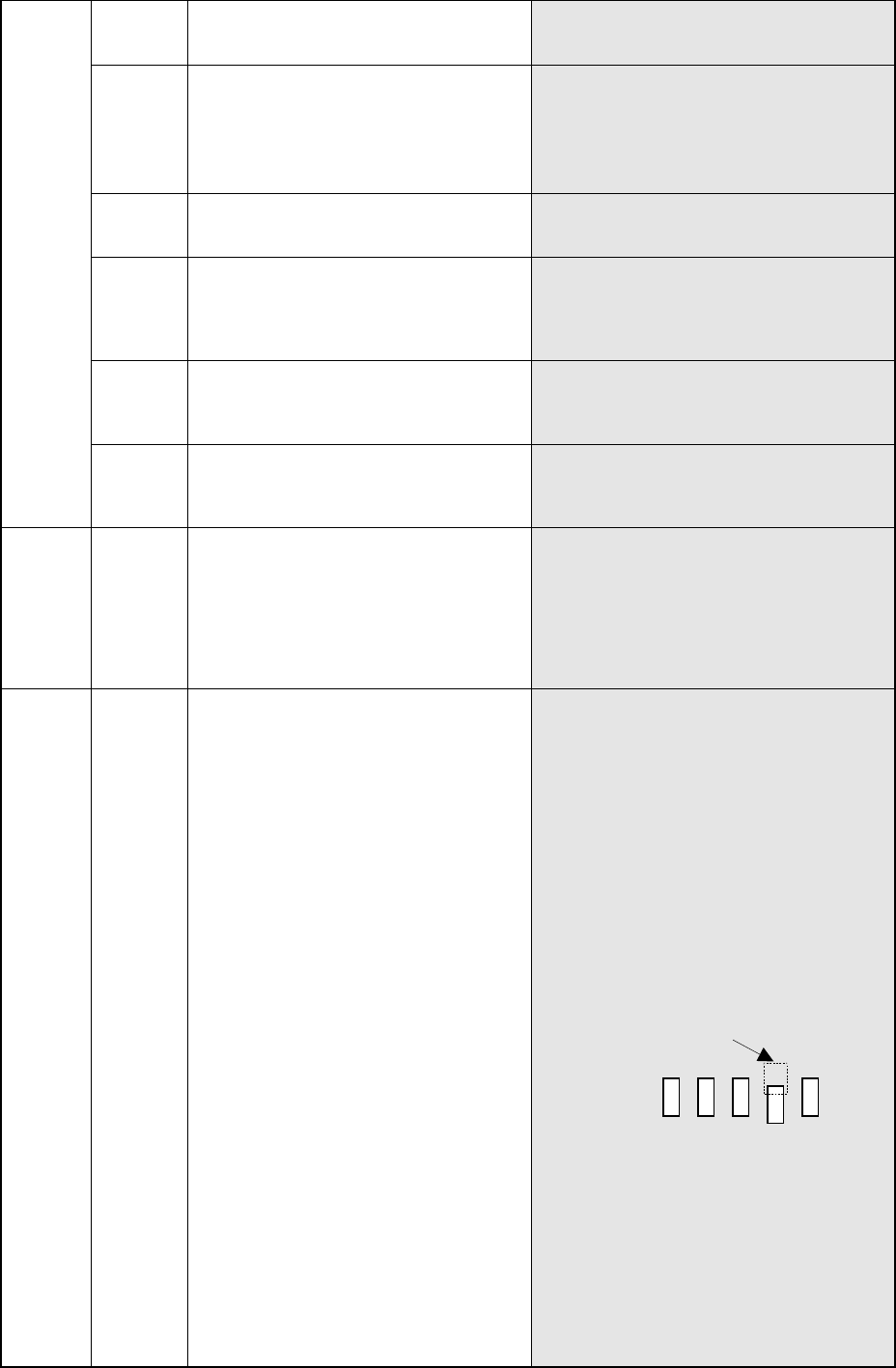
Lead width: W Lead pitch: P
± P (width) ×W (length): range for
detecting a tip of a lead
− If no terminal is missing, the surface of
a terminal may prevent the system
from measuring a component normally.
Change the following parameters, and
try to measure a component again.
①
“Lead Brightness Threshold” of
“Coplanarity Check data”
②
“Scanning Offset” of “Coplanarity
Check data”
③
“Lead Gloss” of “Coplanarity Check
data”
277
5-3130 The image of a terminal is partially
faded.
− This error may occur if the surface of
a terminal does not reflect laser
sufficiently. If you set the smaller
value to the menu item “Electrode
Brightness Threshold” on the
“COPLA CHECK DATA” screen, this
error may not occur again.
5-3140 The image of a terminal is too bright. − This error may occur if the surface of
a terminal reflects laser too much.
If you set the smaller value to the
menu item “Laser Strength” on the
“COPLA CHECK DATA” screen, this
error may not occur again.
FSLS 3-3100 The component tilts.
− This error may occur if a component
tilts due to a component pick-up
error.
FELS 14-9000 Software operation error
− The coplanarity software
malfunctions.
14-14 IP_X board time-out error
− The coplanarity software
malfunctions.
− Electric contact of the coplanarity
232C cable*2 may be poor.
None
14 Mounter time-out error − The IP_X board malfunctions.
− The coplanarity software
malfunctions.
278
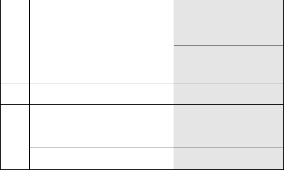
* Coplanarity Cable Connection Diagram
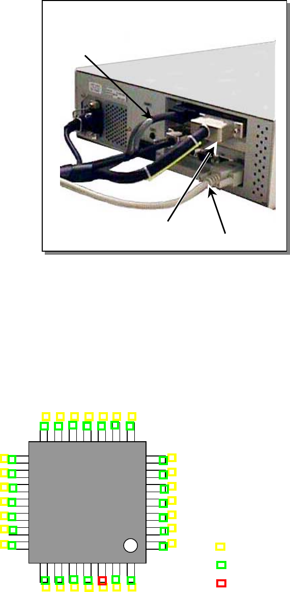
* Coplanarity Error Screen
The coplanarity sensor of a KE-2000 series machine displays the image indicating the
coplanarity check error on the coplanarity screen if a coplanarity error occurs. However,
when the machine finishes a coplanarity check normally, it does not display any image on
the screen so that it cannot affect the cycle time seriously. You can operate the VGA
switch to display such an image on the liquid crystal display monitor
(Front: the screen of the machine Rear: Coplanarity screen).
As shown in the figure below, a yellow rectangle appears on the ideal electrode position
calculated based on the Component data, a green rectangle appears on the electrode that
is checked to be correct, and a red rectangle appears on the electrode on which an error is
detected on the screen. This image is shot from the bottom of the component, but it is
reversed and shown as if the component is shot from the top. The component is supposed
to be checked when its placement angle is 0 degrees.
*3 Coplanarity interface cable
1 Coplanarity sensor cable
*2 Coplanarity 232C cable
Ideal electrode position (yellow)
Normal electrode (green)
Electrode on which an error is detected (red)