KE2010.Instruction Manual.Ver.2.01,Rev.08.pdf - 第159页
4 – 52 Menu display ed when you select the <Ckt. L yt> button Edi t (E) Insert a line ( I) Inserts a blank line at t he cursor position. Cut (T ) Cuts the line at which the input focus is locat ed, then data locate…
4 – 51
⑩ Back Height
Enter the distance from the board transfer reference side to the bottom side of a
PWB including components (note that any component located on the bottom of
a PWB should not interfere with the support table).
The value you entered here is used as the support plate waiting position during
production.
The shorter the support plate moves, the shorter the board transport cycle time
becomes.
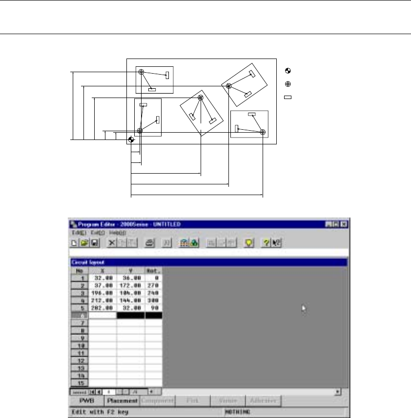
⑪ Circuit layout
When you click the <Ckt. lyt> button, the "Circuit layout" window, which allows
you to enter the circuit layout data, opens. Use the up, down, left and/or right
cursor keys or a track ball to move the cursor, then enter a numeric character.
Enter to the "X" and "Y" columns the distance from the origin of the board to
that of each circuit. Enter to the "Rot." column the angle of each circuit with
assuming that the circuit on which Placement data is created based is located
at 0 degrees and the anti-clockwise direction is positive. After entering data,
click the [Exit] command to return to the "Dimensions" window.
Note: When you select “PWB mark used” as the “BOC type” on the PWB data basic
setting screen, enter a multiple of 90 degrees to the “Rot.” cell.
No.1
No.2
No.4
No.5
No.3
Y5Y1
Y3
Y4Y2
X1
X2
X3
X4
X5
Origin of a board
Origin of a circuit
Component
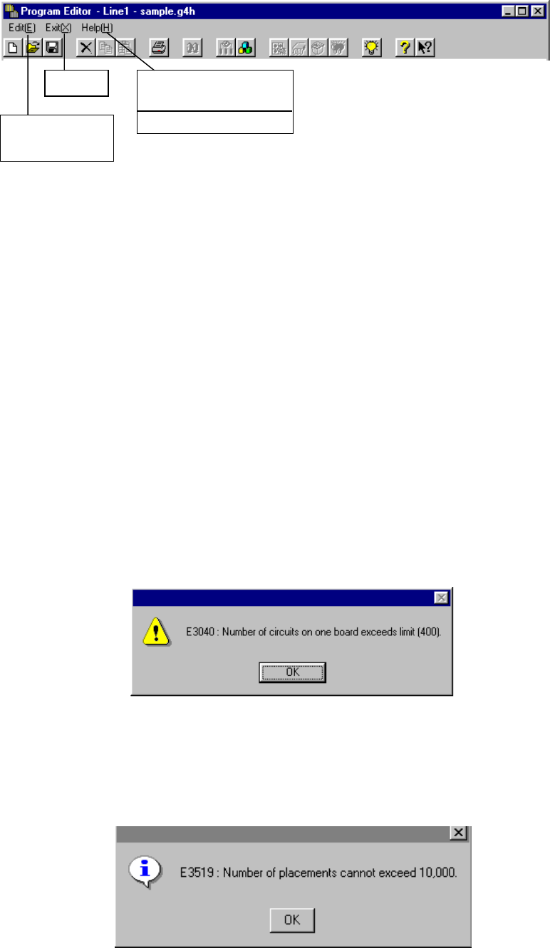
4 – 52
Menu displayed when you select the <Ckt. Lyt> button
Edit (E)
Insert a line (I) Inserts a blank line at the cursor position.
Cut (T) Cuts the line at which the input focus is located, then
data located after the cut line moves upward after
deletion.
Exit (X)
Exit (X) Terminates the circuit layout input operation, then
closes the “Circuit layout” window. Data at incomplete
lines will be deleted.
Help (H)
Command (C) Displays the command help index.
How to use Help (H) Displays how to use the Help functions.
Version information (A) Displays the version of the machine.
When you select “Matrix circuit” as the PWB configuration, the following dialog box
appears on the screen if the total number of circuits exceeds 100.
When you select “Matrix circuit” or “Non-matrix circuit” as the PWB configuration, the
following dialog box appears on the screen if the total number of component
placement positions (total number of circuits X total number of placement data
pieces) exceeds 10,000 even though Placement data has been entered and the
total number of circuits is less than 100.
Exit
Command (C)
How to use Help (H)
Version information
(
A
)
Insert a line (I)
Cut (T) Ctrl
4 – 53
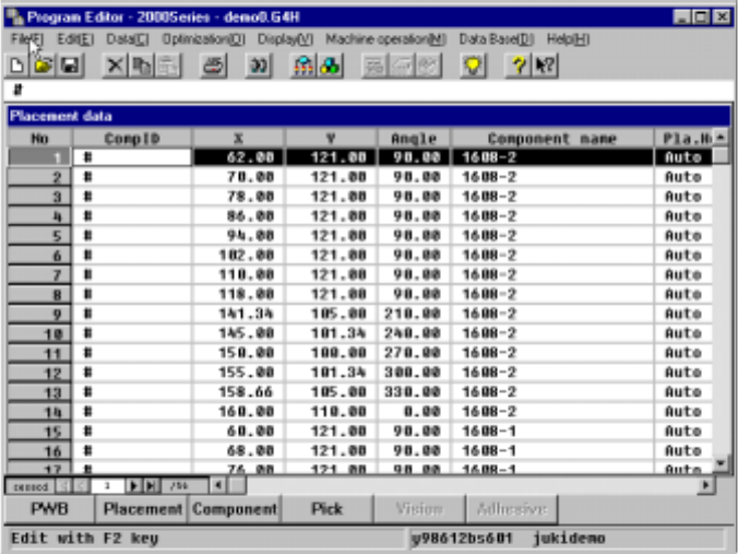
4.6 Placement Data
4.6.1 Basic operation
Start-up screen
The Placement data input screen appears in the form of a list at its start up as
shown below.
The line at which the input focus is located is highlighted, while the cell at which
the input focus is located is not highlighted.
Characters you entered are echoed back in the formula bar, and when you
validate them, they are entered into the cell.
Left-right scroll
The placement data list screen does not show all data at one time. You have to
scroll the screen right to left or vice versa to enter data. When you move to the
right at the rightmost input field, the screen scrolls by one row, then the input
focus moves to the next field.
When you continue scrolling the screen to the right to reach the final column field,
the input focus cannot be moved even though you try to move to the right
direction. To move to the next line, scroll the screen downward.