KE2010.Instruction Manual.Ver.2.01,Rev.08.pdf - 第178页
4 – 71 ④ Outer dim ensions (W idth, Lengt h) Enter the component width and lengt h, using the f ormula bar . Input range: 0.01 mm t o 150.00 mm ⑤ Outer dim ensions (Height ) Enter the component heig ht using the f ormula…
4 – 70
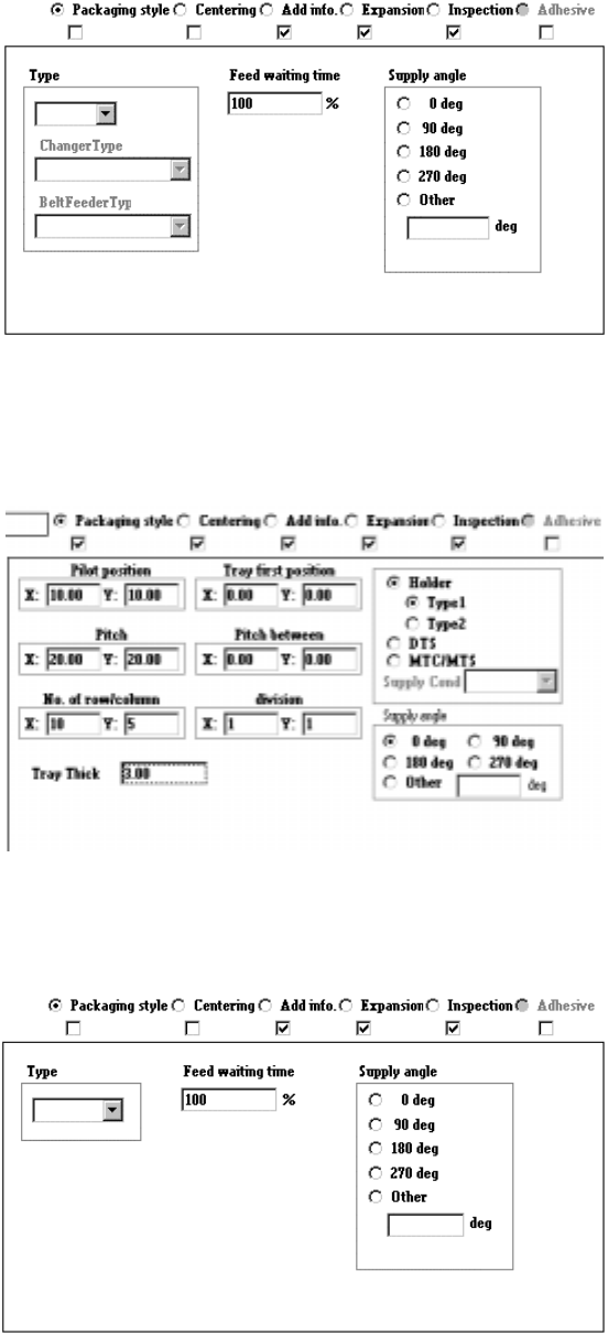
2) Tack control section to be displayed when “Stick” is selected as the component
package
3) Tack control section to be displayed when "Tray" is selected as the component
package
4) Take control section to be displayed when “Bulk” is selected as the component
package
When you change the “Component packaging” setting, the “Sply” (Supply) menu
item of Pick data is set to “Auto”.
4 – 71
④ Outer dimensions (Width, Length)
Enter the component width and length, using the formula bar.
Input range: 0.01 mm to 150.00 mm
⑤ Outer dimensions (Height)
Enter the component height using the formula bar.
Input range: 0 to 25.00 mm
⑥ Other
Pick depth
Enter the distance from the side picked up with a nozzle to the top of the
projection of a component with using the formula bar.
Input range: 0 to 25.00 mm
The default value is “0”. Entry to this item may be required for a
component whose surface is not flat such as a connector.
Normally the default value can be applied to this item.
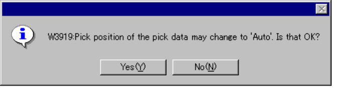
4.7.2.1 Changing Component Data
If you change the Component data although the pickup station or position is
specified on Pick data of a component, the following confirmation message appears
on the screen. When you click the <Yes> button, your change becomes effective.
When you click the <No> button, your change is discarded.
When you click the <Yes> button, all Pick data records of the component is set to
“AUTO.” If you change any item that may cause the allocation position to change
such as the component type, packaging style, tape type, tray supplying method, tray
thickness, tray type, bulk type and stick type that restrict the number of holes to be
occupied or allocation position, the following message appears on the screen.
4 – 72
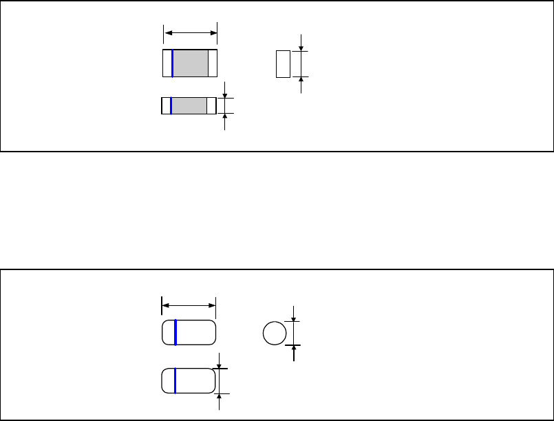
4.7.2.2 Examples of component dimensions
See the following figures to create data.
The dimensions and shape of each type of component are shown below.
• Square chip, Square chip(LED)
• MELF
Dimensions (horizontal)
Dimensions
(Vertical)
Component height
Dimensions (horizontal)
Dimensions
(Vertical)
Component height