KE2010.Instruction Manual.Ver.2.01,Rev.08.pdf - 第188页
4 – 81 4.7.3 Tack control section (Component package page) 1) W hen “T ape” is selected ① T ape w idth Select the appropr iate tape width with the corresponding radio button. ② Feed Pit ch Select the f eed pitch f rom th…
4 – 80
外形寸法 縦
リードピッチ
リード長 縦
外形寸法 横
部品高さ
Lead pitch
Dimensions
Dimensions
Component height
Lead length
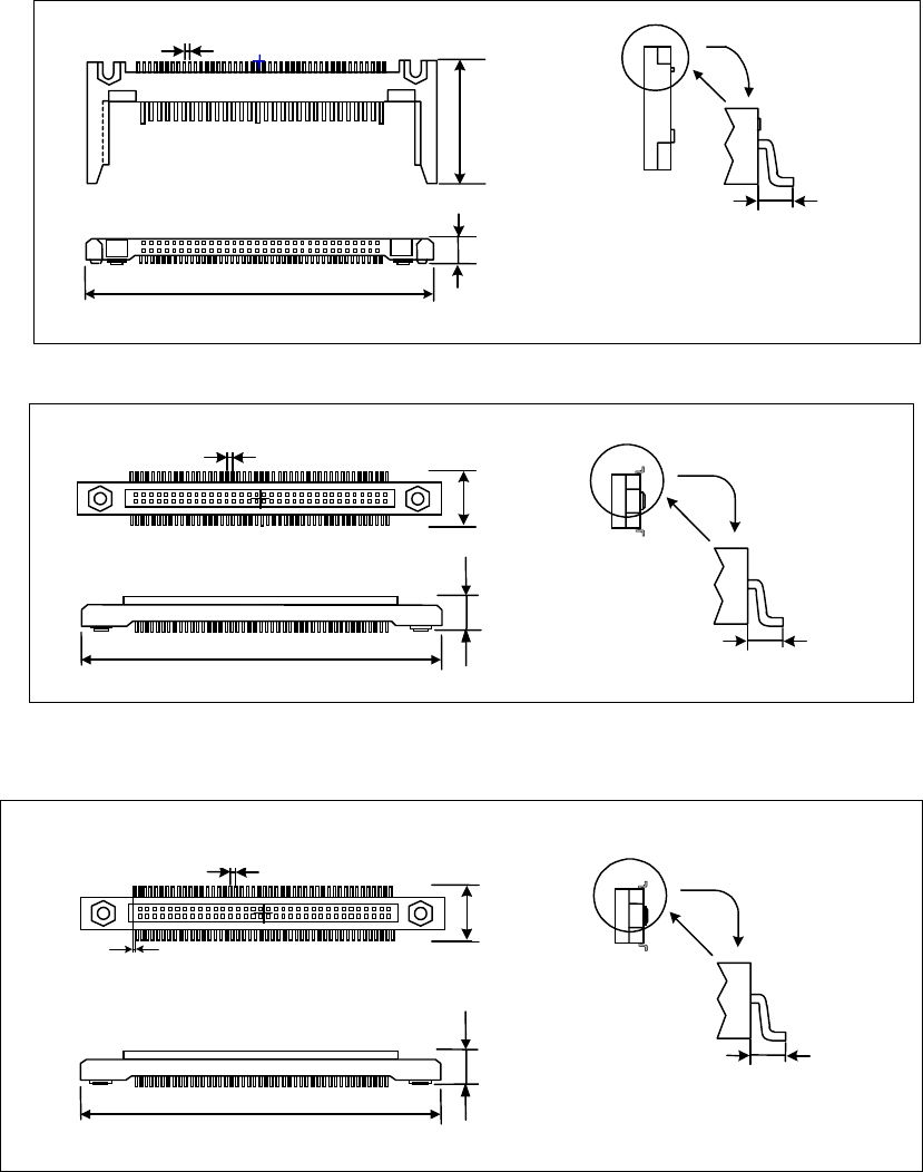
• One-way lead connector
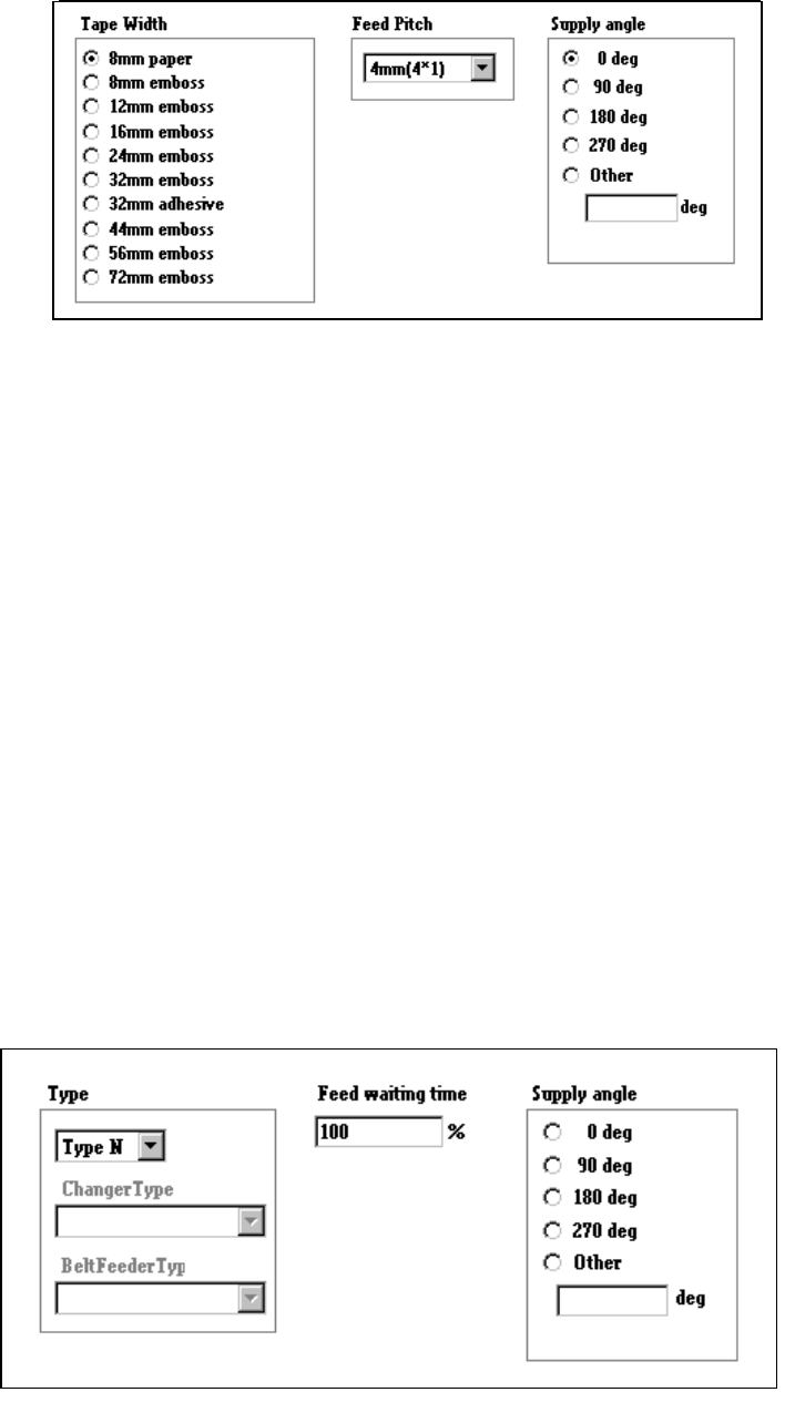
• Two - Way lead connector
• Z lead connector
外形寸法 縦
リードピッチ
下辺リードが右側に半リードピッチシフトしています。
リード長 縦
外形寸法
横
部品高さ
Dimension
Leads located at the bottom side shift
toward the right side in a half of lead.
Dimensions
Component height
Lead length
Lead pitch
外形寸法 縦
リードピッチ
リード長 縦
外形寸法 横
部品高さ
Lead pitch
Dimensions
Component height
Dimensions
Lead length
4 – 81
4.7.3 Tack control section (Component package page)
1) When “Tape” is selected
①
Tape width
Select the appropriate tape width with the corresponding radio button.
②
Feed Pitch
Select the feed pitch from the combo box.
To control the feeder knock pin, the “Feed Pitch” and “Tape Width” settings
are required.
Feed pitches displayed, that is “selectable”, in the combo box vary
depending on the setting of the “Tape Width” item.
③
Supply angle
Specify the angle at which a component is set against the tape feeding
direction: select the desired angle with the corresponding radio button.
When you select “Other” as the component type, enter the angle in the edit
field (0 to 359 degrees). See Section 4.7.9 “Definition of the component
feeding angle”.
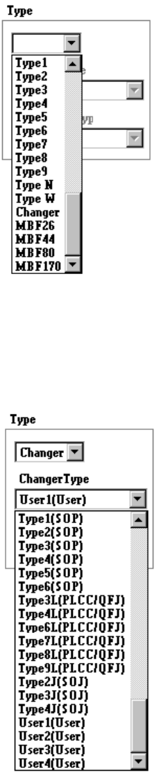
2) When “Stick” is selected
4 – 82
①
Type
Select the stick feeder type.
②
Changer Type
Select the stick changer type.
This item is available only when you select “Changer” at the menu item
“Type” above.