KE2010.Instruction Manual.Ver.2.01,Rev.08.pdf - 第192页
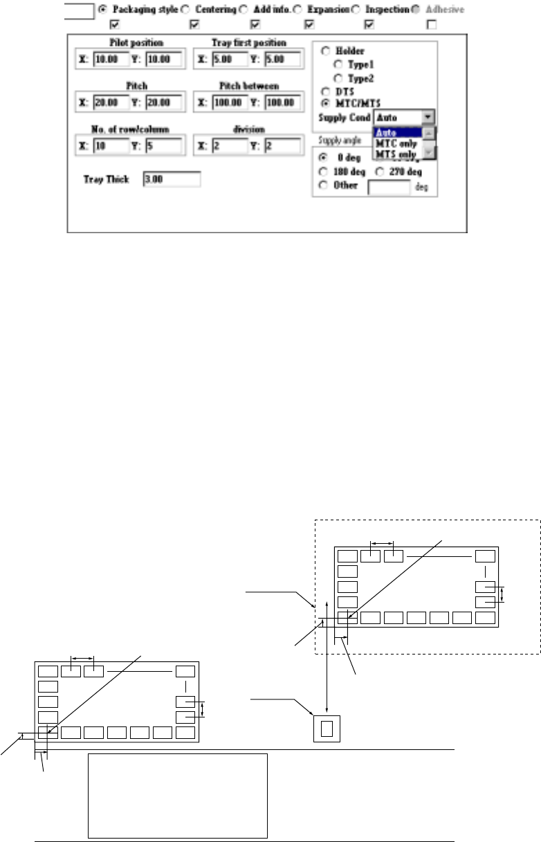
4 – 85 ④ T ray f irst posit ion Enter the dist ance f rom the tray holder edg e to the t ray ref erence position ( X, Y) on the tr ay holder . ⑤ Pitch between Enter the t ray pitch (distance bet ween two consecutive tray…
4 – 84
3) When "Tray" is selected
①
Pilot position
Enter the distance from the tray outline to the center point of the first
component position (X, Y).
②
Pitch
Enter the component pitch (distance between two consecutive components)
(X- and Y-pitch)
③
No. of row/column
Enter the number of components which are located in the X direction and
that in the Y direction (Xn and Yn) respectively.
Yn
Xn
Yn
Xn
MTC
TR4, TR6
Figure 4.7.3.1 First component position, pitch and number of components
Tray holder, DTS, MTS, (TR5)
Pitch X First
Pitch Y
First
component
First
component
position X
Shuttle
PWB Transport path
Pitch X
Pitch
Y
Front of the machine
First component
position X
First
component
position Y
4 – 85
④
Tray first position
Enter the distance from the tray holder edge to the tray reference position (X,
Y) on the tray holder.
⑤
Pitch between
Enter the tray pitch (distance between two consecutive trays) in the holder
(Pitch X, Pitch Y).
⑥
division
Enter the number of horizontal divisions of a tray (Xn) and that of vertical
divisions (Yn).
⑦
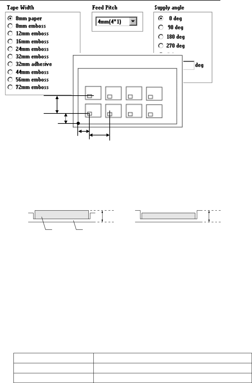
Tray Thick
Enter the height "T" from the bottom of a tray to the top including a
component.
Case 1 Case 2
T T
Figure 4.7.3.2 Tray thickness
⑧
Feeder
Select a feeder with the corresponding radio button.
If you change the "Component packaging" of a component, whose two or
more Pick data records are entered, to a tray, DTS or MTC/MTS, the dialog
box shown below appears on the screen.
When you specify "MTC/MTS", select the feeding condition on the combo
box. The feeding condition specified here is to be referred when you
perform the Optimization utility to divide data or when you specify the stage
of Pick data.
Supply Cond (Feeding condition)
Auto Both the MTC and MTS can be used
MTC only Only MTC can be used.
MTS only Only MTS can be used.
Component Tray
Pitch X
Pitch Y
Y
X
Xn
Yn
4 – 86
⑨ Supply angle
Select the component supply angle with the corresponding radio button.
When you select "Other" as the "Kind of component", enter the appropriate
angle in the Edit field (0 to 359。).
The "Supply angle" indicates the component supply angle based on the assumption
that the component placement angle is 0 degrees. Since a tape component supply
direction is specified in Component data, you do not have to specify its supply angle
for Pick data.The anti-clockwise direction should be the + (positive) direction.This
angle cannot be affected with any component supply position: front side, rear side,
MTC or MTS.
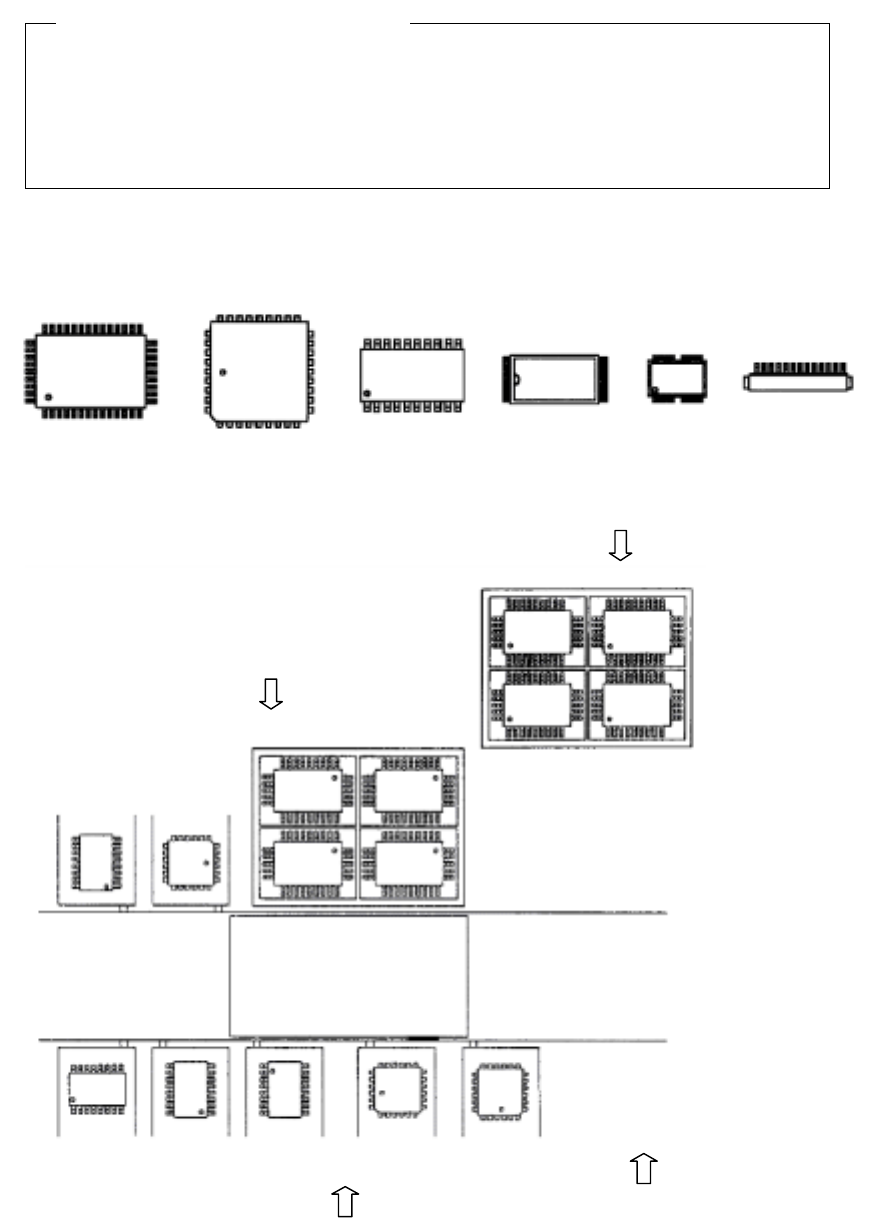
• Supply angle 0。
QFP QFP(PLCC) SOP TSOP-1 TSOP-2 Connector
Figure 4.7.3.3 When the placement angle is 0
。
。。
。
• Example for setting the "Supply angle"
Figure 4.7.3.4 Example of "Supply angle"
Definition of the "Supply angle"
MTC (TR4
、
TR6)
、
MTS (TR5)
QFP
0
°
Tray holder
QFP
0
°
Stick feeder
QFP
0
°
SOP
270
°
SOP
0
°
SOP
90
°
SOP
270
°
QFJ
0
°
QFJ
90
°
Front of a stick feeder
: Direction of the view
which is used for
determining the
"Supply angle"