KE2010.Instruction Manual.Ver.2.01,Rev.08.pdf - 第194页
4 – 87 4) W hen “Bulk” is select ed ① T ype Select the bulk feeder type in the combo box. ② Feed waiting time Set the rat io of t he component f eeding t ime to t he waiting time f or t he next component to be pick ed up…
4 – 86
⑨ Supply angle
Select the component supply angle with the corresponding radio button.
When you select "Other" as the "Kind of component", enter the appropriate
angle in the Edit field (0 to 359。).
The "Supply angle" indicates the component supply angle based on the assumption
that the component placement angle is 0 degrees. Since a tape component supply
direction is specified in Component data, you do not have to specify its supply angle
for Pick data.The anti-clockwise direction should be the + (positive) direction.This
angle cannot be affected with any component supply position: front side, rear side,
MTC or MTS.
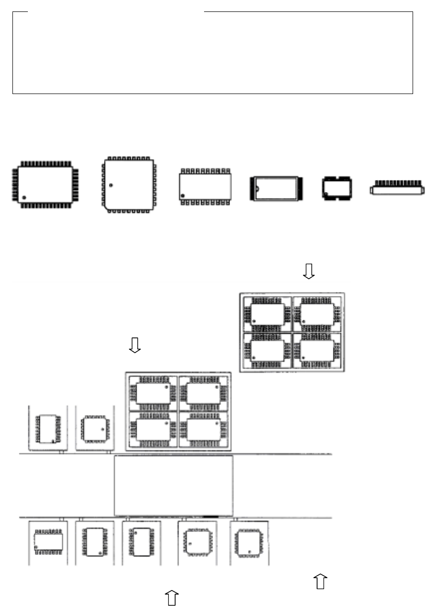
• Supply angle 0。
QFP QFP(PLCC) SOP TSOP-1 TSOP-2 Connector
Figure 4.7.3.3 When the placement angle is 0
。
。。
。
• Example for setting the "Supply angle"
Figure 4.7.3.4 Example of "Supply angle"
Definition of the "Supply angle"
MTC (TR4
、
TR6)
、
MTS (TR5)
QFP
0
°
Tray holder
QFP
0
°
Stick feeder
QFP
0
°
SOP
270
°
SOP
0
°
SOP
90
°
SOP
270
°
QFJ
0
°
QFJ
90
°
Front of a stick feeder
: Direction of the view
which is used for
determining the
"Supply angle"
4 – 87
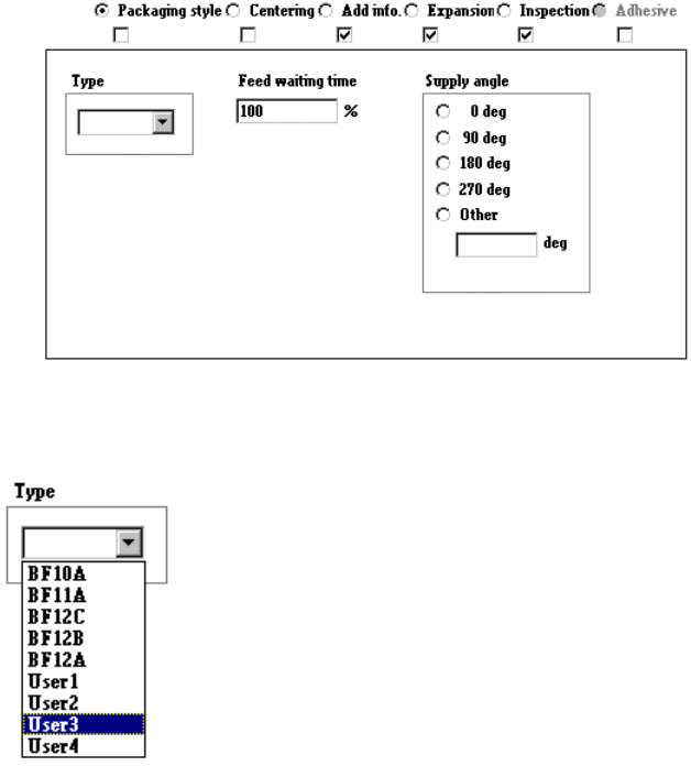
4) When “Bulk” is selected
① Type
Select the bulk feeder type in the combo box.
② Feed waiting time
Set the ratio of the component feeding time to the waiting time for the next
component to be picked up after the current component is picked up. A
unique value is provided to each component type. Specify this unique value
in percentage here.
③ Supply angle
Select the component supply angle with using the corresponding radio
button.
4 – 88
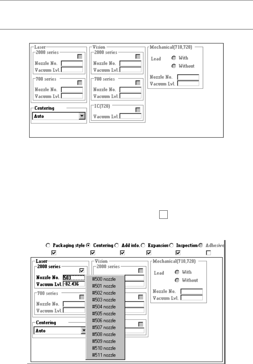
4.7.4 Tack control section (Centering page)
Select “Laser” because this item is specific only to “Laser”.
No other centering method cannot be selected.
Note: When you read data from another machine or database into this machine, the
menu items “Vision” and “Mechanical” are disabled, then Component data
becomes incomplete.
Two menu items “Vision” and “Mechanical” are disabled, so you cannot set any data
for these items.
① Nozzle No.
Directly enter the nozzle number into the edit box or select one from the pop-up
menu which is shown below.
When you press the right button of a track ball or F2 key of a keyboard, the
following pop-up menu appears on the screen. Select the desired nozzle number.