KE2010.Instruction Manual.Ver.2.01,Rev.08.pdf - 第198页
4 – 91 ⑤ Component Specify where to discard a component . - Trash box: available f or all types of components. - Tray restore: available for com ponents whose packing style is a tray . - Trash convey or: available f or c…
4 – 90
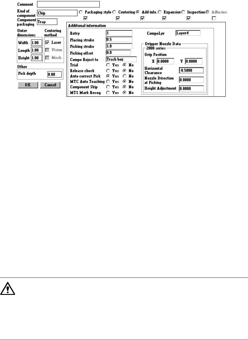
4.7.5 Tack control section (“Add. info.” page)
Since the default values are set at the items provided on the Additional information
page, normally you do not have to change them. Only if you want to change the
default setting, open the Additional Information window. Note that some items may
be reset to their default values if you change settings on the kind of component,
Centering or Component packaging page after you change the setting of items on the
Additional Information page.
●
Additional information
①
Retry
Enter in the edit field the number of retries to be performed when a component
pick-up error occurs. The yellow signal light flashes to warn you when an
overretry occurs in production.
②
Placing stroke
Enter in the edit field the placing stroke for pushing a component from the top of a
board.
③
Picking stroke
Enter in the edit field the picking stroke for pushing the tip of a nozzle to pick up a
component.
④
Picking offset
Enter in the edit field the picking offset for pushing the tip of a nozzle from the
component picking-up height to pick up embossed tape. The system uses this
value to automatically calculate a value of “Z” on the Pick data screen when
“Tape” is selected as the packaging style and embossed tape is selected as the
“Tape Width”.
If you change the “Picking offset” value of this menu even when the
coordinates of the component picking up position are already entered, the
system will not calculate the component pick-up position again. If you change
the setting of “Sply” to “AUTO” on the Pick data corresponding to the
Component data you changed, and specify the pick-up position again, the
system calculates the coordinates of the pick-up position again, and they are
entered to “Z”.
4 – 91
⑤
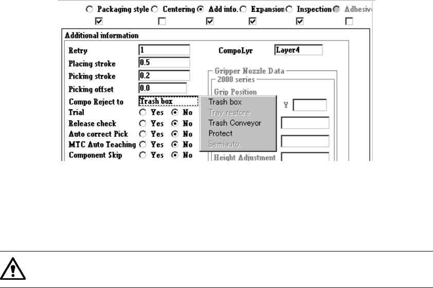
Component
Specify where to discard a component.
- Trash box: available for all types of components.
- Tray restore: available for components whose packing style is a tray.
- Trash conveyor: available for components which can be centered with the VCS.
- Protect: available for all types of components.
If you set “Mecha” in the “Shuttle” cell of the “MTC/MTS/DTS” column on the
Expansion page when an MTC is used, do not set “Tray restore” here.
⑥
Trial
Use the radio whether or not the component is actually placed for trial.
⑦
Release check
This item is available only for a laser centering component, and functions to
check to see with laser if a component remains in the nozzle after the machine
places it on a board. With the corresponding radio button, specify whether to
check to see if a component is released.
Auto correct Pick
⑧
This item is for a laser centering tape component, and functions to correct a
pick-up position error based on the result of the laser recognition operation.
With the corresponding radio button, specify whether to correct a pick-up
position.
⑨
MTC Auto Teaching
When you set this item to “Yes”, the system automatically measures the center of
a component at each regulated point and the spot light indicates the center of a
component. During PWB production, the system automatically performs this
operation when production starts and when a tray is pulled for the first time after
the number of components is changed.
⑩
Component Skip
When you set this item to “Yes”, the specified type of components is skipped and
is not placed on a board. A placement data record specifying a skipped
component is not used for placing components on a board during production, but
is not added to the “Unplaced list”.
− When component information is loaded from the database, data specifying a
skipped component is not loaded to the system.
4 – 92
⑪
MTS Mark Recog. (Recognition)
If you set the “Pick reference position mark” to “Yes” when an MTS is used, the
system recognizes a component pick-up reference position mark when a tray on
which the specified component is located is pulled out, and corrects the actual
coordinates for picking up or returning a component.
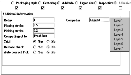
⑫
Component layer
When the same layer is specified as that in Placement data, set the priority
unique to each component.
Set the layers from 0 to 7 on the pop-up menu shown below.
− Nozzle data
Only when you can enter the nozzle number for specifying a nozzle in the
“Centering” field (that is, the corresponding check box is checked), you can enter
this menu item.
The associated initial values of the nozzle data are set every time you enter the
nozzle number.
①
Grip Position
Enter the offset from the center of a component to the center of the
pushed-up surface of the arm located on the gripper nozzle fixed side into
the “Y” field together with a minus sign. Do not enter any figure except “0”
into the “X” field.
②
Horizontal Clearance
Enter the clearance between the pushed-up surface of the arm located on
the gripper nozzle and a component together with a minus sign.
③
Nozzle Direction at Picking
Specify the nozzle direction to be set when it picks up a component that is
supplied at 0 degrees. Enter a figure among 0, 90, 180 and 270.
④
Height Adjustment
Enter a value for correcting the component pick-up height (used together
with the push-up stroke).