KE2010.Instruction Manual.Ver.2.01,Rev.08.pdf - 第200页
4 – 93 4.7.6 Tack control section (Expansion page) Since the def ault values are always set at the items on t he Expansion page, norm ally you do not have to change them. Only if you want to change t he def ault setting …
4 – 92
⑪
MTS Mark Recog. (Recognition)
If you set the “Pick reference position mark” to “Yes” when an MTS is used, the
system recognizes a component pick-up reference position mark when a tray on
which the specified component is located is pulled out, and corrects the actual
coordinates for picking up or returning a component.
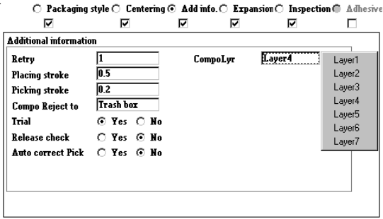
⑫
Component layer
When the same layer is specified as that in Placement data, set the priority
unique to each component.
Set the layers from 0 to 7 on the pop-up menu shown below.
− Nozzle data
Only when you can enter the nozzle number for specifying a nozzle in the
“Centering” field (that is, the corresponding check box is checked), you can enter
this menu item.
The associated initial values of the nozzle data are set every time you enter the
nozzle number.
①
Grip Position
Enter the offset from the center of a component to the center of the
pushed-up surface of the arm located on the gripper nozzle fixed side into
the “Y” field together with a minus sign. Do not enter any figure except “0”
into the “X” field.
②
Horizontal Clearance
Enter the clearance between the pushed-up surface of the arm located on
the gripper nozzle and a component together with a minus sign.
③
Nozzle Direction at Picking
Specify the nozzle direction to be set when it picks up a component that is
supplied at 0 degrees. Enter a figure among 0, 90, 180 and 270.
④
Height Adjustment
Enter a value for correcting the component pick-up height (used together
with the push-up stroke).
4 – 93
4.7.6 Tack control section (Expansion page)
Since the default values are always set at the items on the Expansion page, normally
you do not have to change them. Only if you want to change the default setting,
open this Expansion window. Note that some items may be reset to their default
values if you change items on the Basic, Centering or Component packaging window
after you change the setting of items on the Expansion page.
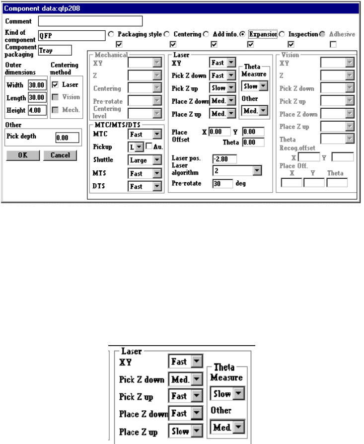
(1) Laser centering
①
XY
Set in the combo box the accelerations of the X and Y axes to move the
component to the placement position after it is picked.
②
Pick Z down
You can select any of the same choices as those displayed in the "XY"
combo box.
This selection is useful to adjust the vertical stress imposed on a component
or adjust shock given to a board.
4 – 94
③
Pick Z up
Using this combo box, set the acceleration (for preventing the components
from dropping) of Z-axis up movement at the pick position.
You can select any of the same choices as those displayed in the "XY"
combo box.
Specify "Med." or "Slow" if the surface area of a component is large, so its air
resistance is high, or if a component is heavy.
④
Place Z down
Using this combo box, set the acceleration (for adjusting the stress placed on
a component) of Z-axis down movement at the placement position.
You can select any of the same choices as those displayed in the "XY"
combo box.
Specify "Med." or "Slow" if a very small component is fed with a tape feeder
and it can be placed unstably.
This selection is useful to adjust the vertical stress imposed on a component
also.
⑤
Place Z up
Using this combo box, set the acceleration (for placing components stably) of
Z-axis up movement at the placement position.
You can select any of the same choices as those displayed in the "XY"
combo box.
⑥
Theta
Using the combo box, set the θ rotation speed.
− test 1 (When measuring)
Set the acceleration of the theta axis to be applied when a component is
recognized with laser.
− test 2 (When not measure)
Set the acceleration of the theta axis to be applied not when a component
is recognized with laser.
You can select any of the same choices as those displayed in the "XY"
combo box.
⑦
Place Offset
Enter the placement offset for unsymmetric components.
⑧
Laser
Enter the offset from the surface of the component to the laser.
This item is enabled only when an LA/LAHD head or MNLA/FMLA head is
used.