KE2010.Instruction Manual.Ver.2.01,Rev.08.pdf - 第205页
4 – 98 W hen y ou click the <Set> butt on, the f ollowing “COPLA CHECK DA T A” dialog box appears on the screen. Inspect Select whether to perform the coplanarity check or not. T olerance Set the value used for jud…
4 – 97
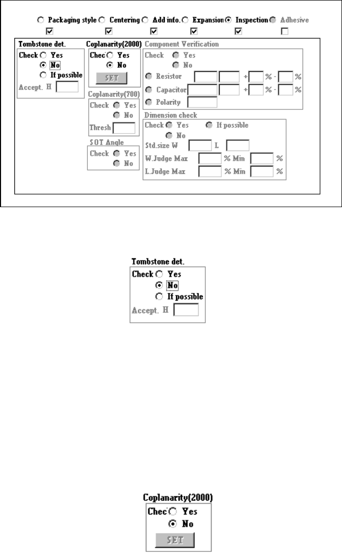
4.7.7 Tack control section (Inspection page)
①
Tombstone det.
Using the radio button, select whether to use the chip rise detecting option.
− When you select the radio button “Yes” or “If possible,” enter the “Accept. H”
filed.
− If you select “If possible”, the machine detects a chip rise error when the chip
rise detecting unit is installed on the machine.
②
Coplanarity (featured in KE-2020 / 2040 only)
Specify whether to check if a lead of a component floats or not with using the
radio button.
− When you check the radio button “YES”, the <Set> button is enabled.
Enter the coplanarity check data.
4 – 98
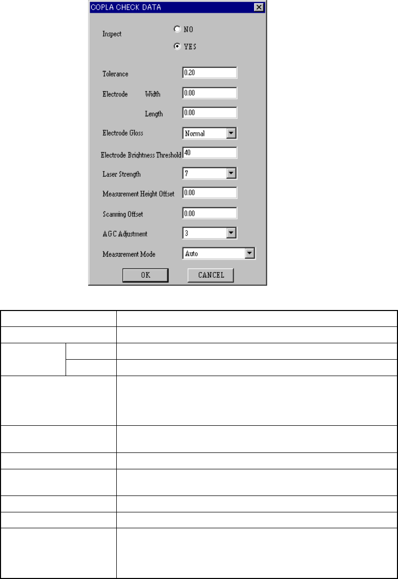
When you click the <Set> button, the following “COPLA CHECK DATA” dialog
box appears on the screen.
Inspect Select whether to perform the coplanarity check or not.
Tolerance Set the value used for judgment.
Width Set the width of the electrode. Electrode
Length Set the length of the electrode.
Electrode Gloss
Set the electrode coating information.
• Normal
• Glossy
• Not glossy
Electrode Brightness
Threshold
Set the threshold value for the brightness of a electrode.
Laser Strength Set the laser strength.
Measurement Height
Offset
Set the offset for the measured height.
Scanning Offset Set the offset for the scanned position.
AGC Adjustment Set the AGC corrected value.
Measurement Mode
Set the measurement mode:
• Auto
• Normal measurement mode
• High-precision measurement mode
Click the <OK> button to validate your settings, or <CANCEL> button to cancel
your settings.
For BGA and FBGA component, it is impossible to set the electrode width and
length, electrode gloss information, and scan position offset value.
4 – 99
③
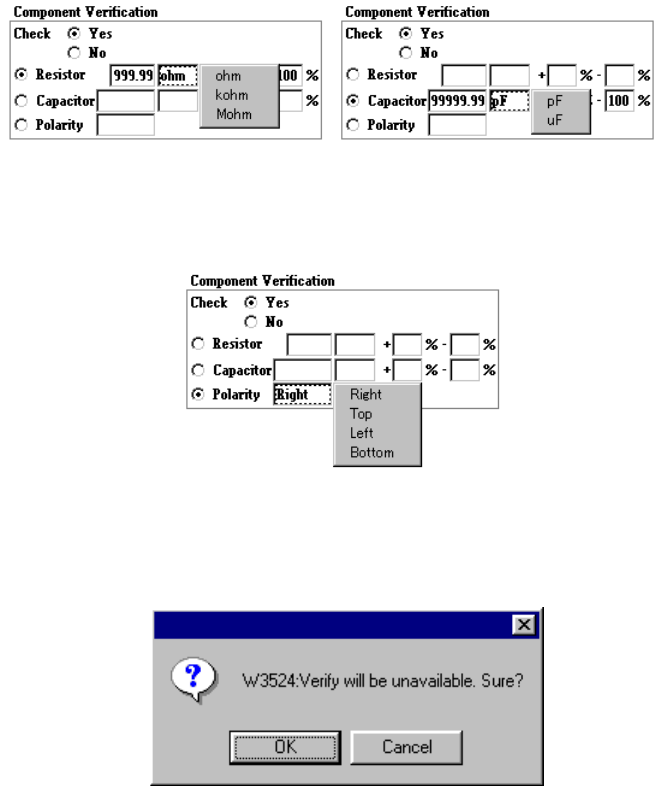
Verify
Using the radio button, select whether to verify a component: resistor, capacitor
and polarity.
When you select “Capacitor” or “Resistor”, enter the upper and lower limits of the
reference value, unit, tolerable error items.
To specify the unit, click the input area with the right button of a mouse. The
following pop-up menu appears on the screen.
When you check the radio button “Polarity”, you can select the direction by
clicking its input area with the mouse right button.
If the Verify check cannot be performed because another data was changed even
though the item “Check” is set to “Yes”, the following dialog box appears on the
screen.
④
Dimension check
Using the radio button, select whether to check the dimensions of a component.
When you select “If possible”, the machine checks the dimensions of a
component.
When you select “Yes”, the machine checks the dimensions of a component.