KE2010.Instruction Manual.Ver.2.01,Rev.08.pdf - 第224页
4 – 1 17 ① Sply (Supply) See the description of "Sply" f or a tape f eeder . ② Angl (Angle) See the description of "Ang le" f or a tape f eeder . ③ Pos (Position) This paramet er sets t he feeder moun…
4 – 116
4.8.2.2 Stick feeder specifications
The stick feeder comes in nine types, and stick changers and belt feeders are also
provided as a stick feeder.
The stick changer comes in 15 types while the belt feeder does in 7 types.
Different types have either one or two or more lanes.
Each stick feeder can have a single type of components on all lanes or different
types for different lanes.
The lane assignment example is shown below.
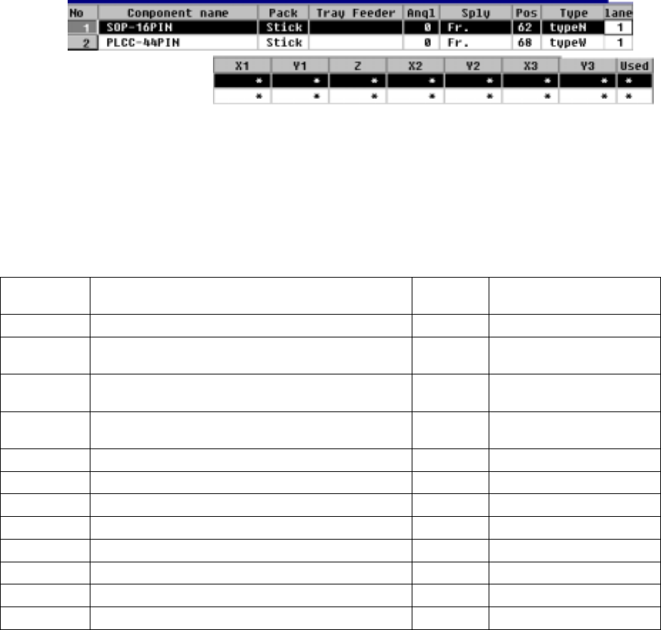
− The parameters "Pack" and "Type" set in Component data appear here: you
cannot change any of them. To change either one, change the setting of
Component data.
Stick feeder types and the number of occupied holes
which are used for mounting each stick feeder
Stick
feeder type
Application
Number
of lanes
Number of holes for
mounting a stick feeder
Type 1 SOP 8, 14 and 16 narrow type 3 8
Type 2
SOP 14 and 16 wide type, SOP 29 narrow type, and
QFJ18
3 8
Type 3
SOP 20 wide type, SOP 24 and 28 narrow type, and
QFPJ20
2 8
Type 4
SOP 24 and 28 narrow type, SOP 32 and higher
narrow type, and QFJ28 and 32
2 8
Type 5 SOP 32 and higher wide type 2 8
Type 6 PLCC42 and 55 2 8
Type 7 PLCC68, 84 and 52 1 8
Type 8 Special type for export 8 8
Type 9 Special type for export 8 8
Type N SOP, SOJ, QFJ (PLCC) N1 to N4 1 8
Type W SOP, SOJ, QFJ (PLCC), W1 to W5 1 6
Changer Stack stick feeder types 1 to 6, 3L to 9L, and 2J to 4J 1 3
4 – 117
① Sply (Supply)
See the description of "Sply" for a tape feeder.
② Angl (Angle)
See the description of "Angle" for a tape feeder.
③ Pos (Position)
This parameter sets the feeder mounting hole number into which the stick
feeder positioning pin is inserted.
− When a number is changed, the parameters to the right of “Pos” are
initialized, then become blank.
As soon as a number is entered, overlap is checked for the existing tape
feeders, tray holders and bulk feeders. If the same number already exists,
the entry is rejected with an error message shown on the screen.
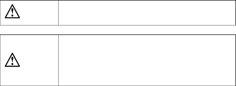
④ Lane
This parameter is used to specify the lane.
− The lanes are numbered 1, 2, 3... from the left, facing the machine, both on
the front and rear sides. See the figure below.
If a lane is already occupied, the entry is rejected with an error message
shown.
Note that this “Lane” parameter cannot be entered in Pick data when you
select a stick changer, and it becomes disabled, and an asterisk mark “*”
appears.
Lane 3 Lane 2 Lane 1 Lane 2 Lane 1 Lane 1
Feeder mounting holes
Transport path
Lane 1 Lane 2 Lane 1
Lane 1
Example of lane numbers assignment
4 – 118
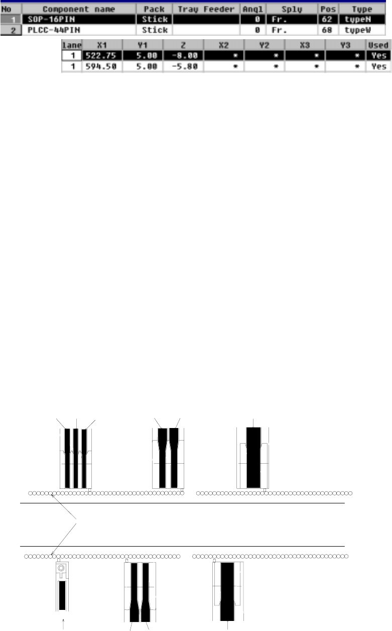
⑤ X1, Y1, Z
These parameters set the coordinates of the feeder component pickup position.
When the items “Sply”, “Pos”, “Type”, and “Lane” are set, these values are
automatically calculated and shown. Once a value is entered to each coordinate,
you can change it (by teaching also).
CAUTION
To avoid a risk of injury, do not place your hand in the machine, nor
move your face or head close to the machine while the machine is
performing teaching operation.
CAUTION
If the bank is never recognized (since the machine zeroes, or the bank
moves down then up), it may be recognized automatically before the
machine moves to the pick position. Since the head moves across the
feeder while the feeder bank is being recognized, do not place your
hand in the machine, nor move your face or head to the machine.
Especially, take care when the feeder bank is recognized not from the
menu but during teaching or tracking a pick position.