KE2010.Instruction Manual.Ver.2.01,Rev.08.pdf - 第232页
4 – 125 ③ Pos (Position) For an MTC/MTS, specif y the level on which a tray component is to be stored. • If you enter the number t o which a tray is already assigned, an overlap error is displayed on the screen and your …
4 – 124
4.8.2.3.3 Matrix tray changer/Matrix tray server (MTC/MTS)
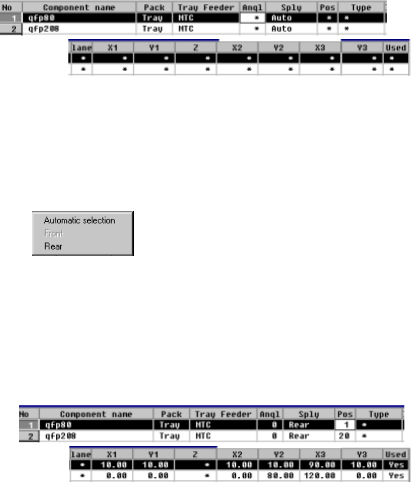
When you select an MTC/MTS, the following screen is displayed.
− The parameters "Pack" and "Tray Feeder" set as Component data appear
here: you cannot change any of them. To change either one, change the
setting of Component data.
① Sply (Supply)
Specify whether a tray is automatically selected or set on the rear side.
The Optimization utility automatically assigns trays to the machine.
Trays are assigned to the rear side.
• When you select "Automatic selection", the Optimization utility automatically
assigns trays to the machine, so you do not have to enter any data to other
items.
• When the Optimization utility is executed, items at which an asterisk mark
"*" is displayed (excluding the parameter "Lane") are automatically set.
When you select "Rear", you can enter data to the items at which an
asterisk mark is displayed (excluding the parameter "Lane").
② Angl (Angle)
See the description of the parameter "Angl" for a tape/bulk feeder.
4 – 125
③ Pos (Position)
For an MTC/MTS, specify the level on which a tray component is to be stored.
• If you enter the number to which a tray is already assigned, an overlap error
is displayed on the screen and your entry is rejected.
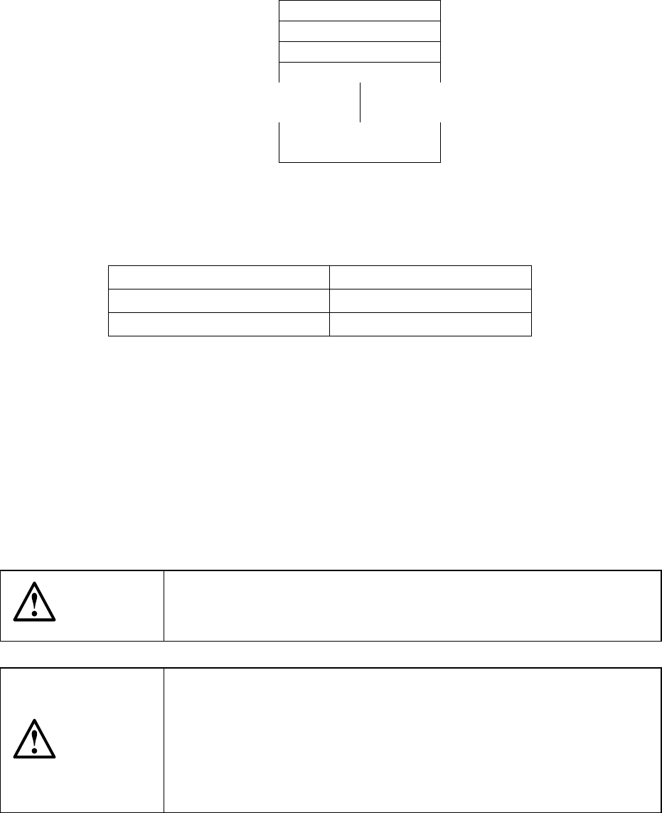
• For an MTS, the number of levels which are to be occupied changes
depending on the "tray thickness" set as Component data.
If a tray cannot be assigned to the desired level because the level(s) above
and/or below are occupied, an error is displayed and your entry is rejected.
Level 1
Level 2
Level 3
Level 4
Levels 20 to 40
Figure 4.8.2.3.3.1 Number of levels of an MTC/MTS
Number of occupied trays
Tray thickness set Number of levels occupied
0.00 mm to 8.99 mm one level
9.00 mm to 23.00 mm two levels
④ X1, Y1, Z, X2, Y2, X3, Y3
Specify the component pick-up position at three corners of a tray.
When you set the parameter "Sply", the pick-up position is automatically
calculated, then displayed based on the specifications of Component data.
When a value is entered to each coordinate, you can change each coordinate
(by teaching also).
⑤ Used
See the description of this parameter for a tape/bulk feeder.
CAUTION
To avoid a risk of injury, do not place your hand in the machine, nor
move your face or head close to the machine while the machine is
performing teaching operation.
CAUTION
If the bank is never recognized (since the machine zeroes, or the bank
moves down then up), it may be recognized automatically before the
machine moves to the pick position. Since the head moves across the
feeder while the feeder bank is being recognized, do not place your
hand in the machine, nor move your face or head to the machine.
Especially, take care when the feeder bank is recognized not from the
menu but during teaching or tracking a pick position.
4 – 126
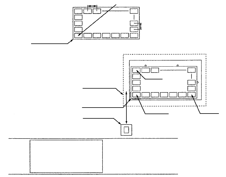
a. MTC (tray changer)
Figure 4.8.2.3.3 How to calculate the pick-up position on an MTC
− When you select an MTC as the parameter "Sply", an asterisk mark "*"
appears in parameters you do not have to enter. The component pick-up
position of an MTC, X1, Y1, Z, X2, Y2, X3 and Y3 are calculated based on the
specifications of a tray stored in Component data and according to the MTC
coordinate system.
− The MTC component pick-up position on the main unit is determined
according to the settings of the Machine Setup menu.
Tray contact position
Pitch X
Pitch Y
Tray contact position
Shuttle
MTC
(TR4, TR6)
PWB PWB transport path
Front of the machine
(X2, Y2)
(X3, Y3) (X1, Y1)
First component position