KE2010.Instruction Manual.Ver.2.01,Rev.08.pdf - 第236页
4 – 129 4.9.2 Line coherence check (1) W hen to invoke the check comm and W hen invoking the Optimization utility Interrupts the next process w hen an error occurs. Arbitrary invoking Y ou can invoke the data coherence c…
4 – 128
4.9 Checking Data Completion Status
4.9.1 Data completion status
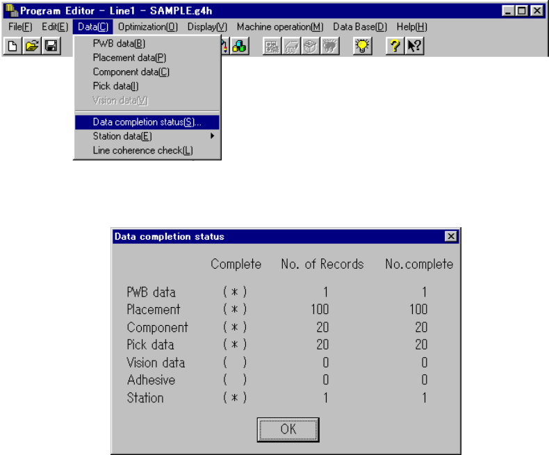
Invoke this command from the Data menu.
When you click the [Data completion status] command, the following dialog box
appears on the screen.
The dialog box shown above displays the number of input records as the menu item
“No. of Records”, the number of completed records as the menu item “No. complete”,
and whether each type data is completed or not as the menu item “Complete”.
Each display item is described below:
① Complete
Displays whether each type of data is completed or not.
(*) data is completed.
( ) data is not completed.
If the value of the menu item “No.of Records” is equal to that of “No. complete”,
the data is handled as “completed”.
② No. of Records
Displays the number of input records regardless of whether each record is
completed or not, that is, displays the total number of records including
incomplete records.
③ No. of complete
Displays the number of records entered completely, that is, displays the number
of records whose necessary items are all entered.
When you click the <OK> button, the machine returns to the data screen from
which you invoked this command.

4 – 129
4.9.2 Line coherence check
(1) When to invoke the check command
When invoking the Optimization utility Interrupts the next process when an error occurs.
Arbitrary invoking
You can invoke the data coherence check by selecting the menu
command when you want to.
(2) Report of the check result
Notification
Notification of the successful check
Notification of a warning
Notification of an error
Error list
Number of errors
Error information: Error position (data type, data number, item
name), and cause of errors
Display and print of the error list To be performed with the standard tool provided with Windows
(3) Coherence check items: error conditions
The chip shooter name becomes effective as the model name in the error
conditions.
Data type Item Error conditions
Positioning method
Although “Shape reference” is selected as “Positioning method”
on the PWB data screen, the positioning method of the machine
is not set to the “Shape reference” method physically.
BOC Type
Although the item “BOC Reference” is set to be used, the OCC-L
of the KE-2010 or “OCC-L” or “OCC-R” of the
KE-2020/2030/2040 is not set to be used.
Mark pattern matching
Although the mark data is set to use the mark pattern matching
function, the VCS is not set to “JVS2” or “JVS3”.
PWB data
Bad mark type The item “Bad mark type” is not set to be used.

4 – 130
(3-1) Coherence check items: error conditions
Data type Item Error conditions
Placement point(s)
The machine calculates the placement range for each
current centered component to check to see if the
placement point is within the range each axis can move.
This range is defined by performing “OR” with the axis
movable range.
*1
Placement station(s)
The machine checks the coherence with using the profile
of the specified station.
*1
Placement of vision
components
The FMLA head is set to “Not used”. *1
Placement of vision
components (over 0.38 mm)
(Lead components).
The standard VCS or optional VCS (37.5 mm, 27 mm or
18 mm) is not set in Placement data of vision components
whose size is 0.38 mm or larger.
*1
Placement of vision
components (0.3 <= Pitch <
0.38 mm) (Lead
components)
The optional VCS (37.5 mm, 27 mm or 18 mm) is not set
in Placement data of vision components whose size is 0.3
mm or larger, but smaller than 0.38 mm.
*1
Placement of vision
components (0.2 <= Pitch <
0.3 mm) (Lead components)
The optional VCS (27 mm or 18 mm) is not set in
Placement data of vision components whose size is 0.2
mm or larger, but smaller than 0.3 mm.
*1
Placement of vision
components ( 0.135 <=
Pitch < 0.2 mm) (Lead
components)
The optional 18 mm VCS is not set in Placement data of
vision components whose size is 0.135 mm or larger, but
smaller than 0.2 mm.
*1
Placement of general vision
components (15 < the
smallest pitch <= 22 mm)
(Lead components)
The standard VCS is not set in Placement data of general
vision components whose minimum pitch is wider than 15
mm, but 22 mm or narrower.
*1
Placement of general vision
components (11 < the
smallest pitch <= 15 mm)
(Lead components)
The standard VCS or optional 37.5 mm VCS is not set in
Placement data of general vision components whose
minimum pitch is wider than 11 mm, but 15 mm or
narrower.
*1
Placement of general vision
components (6.5 < the
smallest pitch <= 11 mm)
(Lead components)
The standard VCS or optional 37.5 mm or 27 mm VCS is
not set in Placement data of general vision components
whose minimum pitch is wider than 6.5 mm, but 11 mm or
narrower.
*1
Placement of general vision
components (0.5 < the
smallest pitch <= 6.5 mm)
(Lead components)
The standard VCS or optional 37.5 mm, 27 mm or 18 mm
VCS is not set in Placement data of general vision
components whose minimum pitch is 0.5 mm or wider, but
6.5 mm or narrower.
*1
Placement of general vision
components (0.4 < the
smallest pitch <= 0.5 mm)
(Lead components)
The optional 37.5 mm, 27 mm or 18 mm VCS is not set in
Placement data of general vision components whose
minimum pitch is 0.4 mm or wider, but narrower than 0.5
mm.
*1
Placement of general vision
components (0.3 < the
smallest pitch <= 0.4 mm)
(Lead components)
The optional 27 mm or 18 mm VCS is not set in
Placement data of general vision components whose
minimum pitch is 0.3 mm or wider, but narrower than 0.4
mm
*1
Placement of general vision
components (0.2 < the
smallest pitch <= 0.3 mm)
(Lead components)
The optional 18 mm VCS is not set in Placement data of
general vision components whose minimum pitch is 0.2
mm or wider, but narrower than 0.3 mm
*1
Placement
data
Placement of vision
components (2 < the
smallest pitch <= 3 mm)
(Ball components)
The standard VCS is not set in Placement data on vision
components whose minimum pitch is wider than 2 mm,
but 3 mm or narrower.
*1
*1: Items applicable to machines other than a KE-2010