KE2010.Instruction Manual.Ver.2.01,Rev.08.pdf - 第240页
4 – 133 Data ty pe Item Error conditions Placement data Placement layer (for a KE-2030) W hen the “Sequential and Mix M ode” is selected at the menu item “2030 Mode Specification” on the “2000 O ption” tab, and “Use manu…
4 – 132
Data type Item Error conditions
Placement of general vision
components
If the specified vision processor whose model is earlier than
JVS3 is specified in the placement data on a general-purpose
vision component.
Placement of an SOT
component whose direction is
checked
If an SOT direction-checking table is not enabled in the
placement data on an SOT component whose direction is
checked.
Placement head
The specified head is set to “Not used” in the station profile.
If “Parallel Mode” is selected at the menu item “2030 Mode
Specification” on the “2000 Option” tab of the “Optimization”
menu, and the placement head of only side is available (“Lx”
or “Rx”).
Placement head
(for a KE-2030)
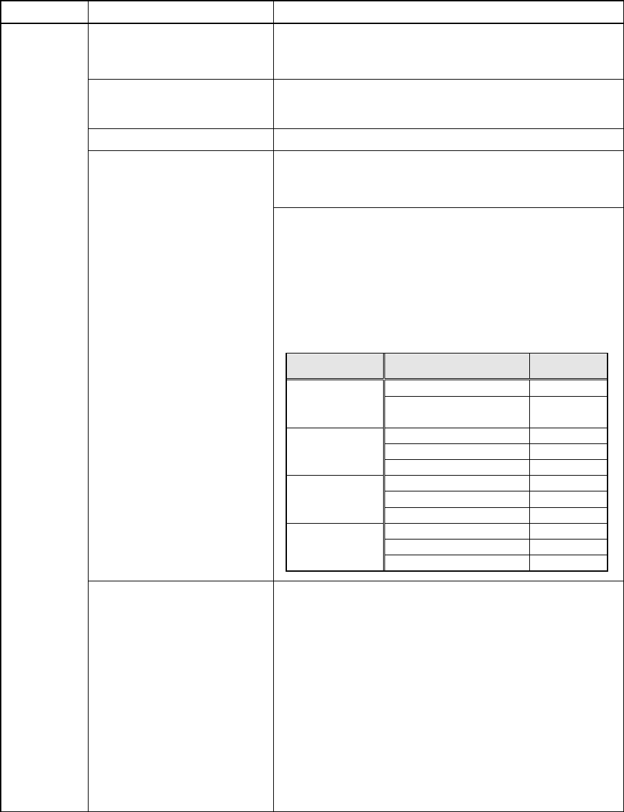
If “Sequential and Mix Mode” is selected at the menu item
“2030 Mode Specification” on the “2000 Option” tab, “Use
manual station/position assignments” as the menu item “Pick
Data” of the “Assignments” tab of the “Optimization” menu,
and all component pick-up positions are specified, the
machine checks to see if the specified placement head is
consistent with the component pick-up position specified in
Pick data.
<Combination of a placement head/pick data causing an
error>
Placement
data
Component Discarding
The component discarding operation that cannot be handled
with a station specified in Placement data is set as described
below:
− “Compo Reject to” is set to “Trash conveyor”, but no IC
recovery belt is installed on the machine.
− “Compo Reject to” is set to “Tray Restore”, but any tray
feeder (see Note) for receiving a returned component is
not installed on the machine.
− “Compo Reject to” is set to “Tray Restore”, “Shuttle” is set
to “Mecha”, and “MTC” is specified as a station.
Note: Tray feeders supporting the “Tray Restore” setting are
as follows:
− MTC: TR6S, TR6D and TR4S
− MTS: TR5S and TR6S
− Tray holder: all of types
− DTS
Placement head Pick data
Consistency
check
Only one side is specified.
×
LxRx
(x includes the
heads
automatically set.)
Both stations are specified.
○
Only the left side is specified.
○
Only the right side is specified.
×
Lx
(x includes the
heads
automatically set.)
Both stations are specified.
○
Only the left side is specified.
×
Only the right side is specified.
○
Rx
(x includes the
heads
automatically set.)
Both stations are specified.
○
Only the left side is specified.
○
Only the right side is specified.
○
Automatically set
Both stations are specified.
○
4 – 133
Data type Item Error conditions
Placement
data
Placement layer
(for a KE-2030)
When the “Sequential and Mix Mode” is selected at the menu
item “2030 Mode Specification” on the “2000 Option” tab, and
“Use manual station/position arrangements” as the menu
item “Pick Data” of the “Assignments” tab of the
“Optimization” menu, and all component pick-up positions are
specified, an error occurs if the In and OUT stations are not
specified in this order as the layer assignment order of the IN
station and OUT station on Placement data respectively.
* When the component placement head is automatically set,
the machine obtains information on the specified station
from Pick data.
If both of the stations have the specified component
placement heads, those heads pass the layer check.
Maximum PL value on the IN side
≦
Minimum simultaneous
placement PL value
≦
Maximum simultaneous placement PL
value
≦
Minimum PL value on the OUT side
PL: placement layer number
*1: Items applicable to machines other than a KE-2010
4 – 134
(3-2) Coherence check items: error conditions
Data type Item Error conditions
Any centering method which allows placement is not set. Centering method
The standard VCS and optional VCS are not available for
vision centering.
*1
Component package
Although the “Packaging style” is set in Component data
of tray components, the item “Packaging style” cannot be
set to “Tray”.
*1
If the “Parallel Mode” is selected at the menu item “2030
Mode Specification” of the “2000 Option” tab, “Use
permanent nozzle setup from MSL Setup” is selected at the
menu item “Nozzle” of the “Assignments” tab of the
“Optimization” menu, and a nozzle specified on the
Component data screen does not exist on both of the
stations.
If the “Parallel Mode” is selected at the menu item “2030
Mode Specification” of the “2000 Option” tab, “Auto arrange
empty nozzle positions” is selected at the menu item “Nozzle”
of the “Assignments” tab of the “Optimization” menu, a nozzle
specified on the Component data screen does not exist on
both of the stations, and there is no not-occupied ATC
position.
If the “Sequential and Mix Mode” is selected at the menu item
“2030 Mode Specification” of the “2000 Option” tab, “Use
permanent nozzle setup from MSL Setup” is selected at the
menu item “Nozzle” of the “Assignments” tab of the
“Optimization” menu, “AUTO” is selected at the menu item
“SPLY” (supply) of any component on the Pick data screen
that is associated with Component data, and a nozzle
specified on the Component data screen does not exist on
both of the stations.
Nozzle (for a KE-2030)
If the “Sequential and Mix Mode” is selected at the menu item
“2030 Mode Specification” of the “2000 Option” tab, “Auto
arrange empty nozzle positions” is selected at the menu item
“Nozzle” of the “Assignments” tab of the “Optimization” menu,
“AUTO” is selected at the menu item “SPLY” (supply) of any
component on the Pick data screen that is associated with
Component data, and a nozzle specified on the Component
data screen does not exist on both of the stations.
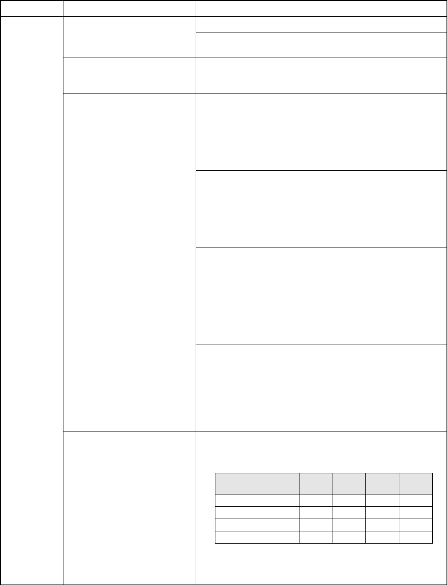
Component
data
Component dimensions
The dimensions set in Component data cannot be handled
with the machine.
<Error conditions>
Note:
△
means that the indicated component height is
applicable if the component height is set to "20 mm" on the
MS Parameter menu of a chip shooter/mounter.
Component
height
2010 2020 2030 2040
0 < H ≦ 6 mm ○ ○ ○ ○
6 < H ≦ 12 mm △ ○ ○
12 < H ≦ 20 mm △ △ ○
20 < H ≦ 25 mm ○