KE2010.Instruction Manual.Ver.2.01,Rev.08.pdf - 第257页
4 – 150 General-purpose vision component (mark component) for which an optional 27-mm VCS is selected in Control data Component whose element siz e X is from 0.7 mm to 1.0 mm or from 5.0 mm to 10.0 mm if an optional 27-m…

4 – 149
General-purpose vision component (ball
component) for which an optional
37.5-mm VCS is selected in Control
data
Component whose element pitch is from 0.35mm to 0.8 mm or
from 15.0 mm to 22.0 mm if an optional 37.5-mm VCS is set in
Control data
General-purpose vision component (ball
component) for which an optional
27-mm VCS is selected in Control data
Component whose element pitch is from 0.35 mm to 0.5 mm or
from 11.0 mm to 22.0 mm if an optional 27-mm VCS is set in
Control data
General-purpose vision component (ball
component) for which an optional
18-mm VCS is selected in Control data
Component whose element pitch is from 6.5 mm to 22.0 if an
optional 18-mm VCS is set in Control data
General-purpose vision component
(lead component) for which the
standard VCS is selected in Control
data
Component whose element size X is from 0.08 mm to 0.22 mm if
the standard VCS is set in Control data
General-purpose vision component
(lead component) for which an optional
37.5-mm VCS is selected in Control
data
Component whose element size X is from 0.08mm to 0.15 mm or
from 7.7 mm to 11.0 mm if an optional 37.5-mm VCS is set in
Control data
General-purpose vision component
(lead component) for which an optional
27-mm VCS is selected in Control data
Component whose element size X is from 0.08 mm to 0.11 mm or
from 5.5 mm to 11.0 mm if an optional 27-mm VCS is set in Control
data
General-purpose vision component
(lead component) for which an optional
18-mm VCS is selected as Control data
Component whose element size X is from 3.7 mm to 11.0 if an
optional 18-mm VCS is set in Control data
General-purpose vision component
(lead component) for which the
standard VCS is selected in Control
data
Component whose element size Y is from 0.14 mm to 0.4 mm if
the standard VCS is set in Control data
General-purpose vision component
(lead component) for which an optional
37.5-mm VCS is selected in Control
data
Component whose element size Y is from 0.14mm to 0.3 mm or
from 14.0 mm to 20.0 mm if an optional 37.5-mm VCS is set in
Control data
General-purpose vision component
(lead component) for which an optional
27-mm VCS is selected in Control data
Component whose element size Y is from 0.14mm to 0.2 mm or
from 10.0 mm to 20.0 mm if an optional 27-mm VCS is set in
Control data
General-purpose vision component
(lead component) for which an optional
18-mm VCS is selected in Control data
Component whose element size Y is from 7.0 mm to 20.0 mm if an
optional 18-mm VCS is set in Control data
General-purpose vision component (ball
component) for which the standard VCS
is selected in Control data
Component whose element size is from 0.14 mm to 0.4 mm if the
standard VCS is set in Control data
General-purpose vision component (ball
component) for which an optional
37.5-mm VCS is selected in Control
data
Component whose element size is from 0.14mm to 0.3 mm or from
3.5 mm to 5.0 mm if an optional 37.5-mm VCS is set in Control
data
General-purpose vision component (ball
component) for which an optional
27-mm VCS is selected in Control data
Component whose element size is from 0.14 mm to 0.2 mm or
from 2.5 mm to 5.0 mm if an optional 27-mm VCS is set in Control
data
General-purpose vision component (ball
component) for which an optional
18-mm VCS is selected in Control data
Component whose element size is from 1.5 mm to 5.0 mm if an
optional 18-mm VCS is set in Control data
General-purpose vision component
(mark component) for which the
standard VCS is selected in Control
data
Component whose element size X is from 0.7 mm to 2.0 mm if
the standard VCS is set in Control data
General-purpose vision component
(mark component) for which an optional
37.5-mm VCS is selected in Control
data
Component whose element size X is from 0.7mm to 1.4 mm or
from 7.0 mm to 10.0 mm if an optional 37.5-mm VCS is set in
Control data
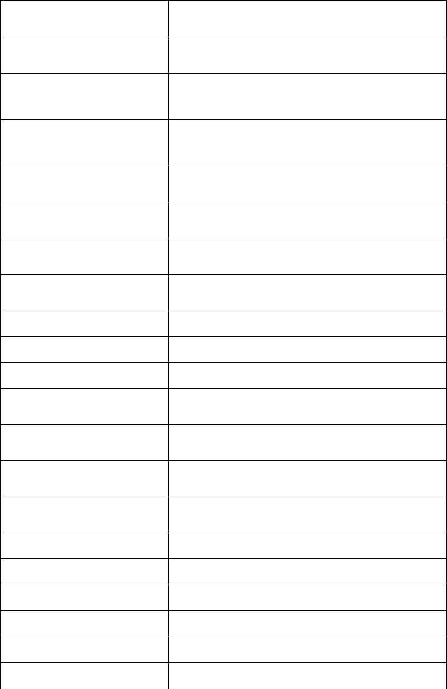
4 – 150
General-purpose vision component
(mark component) for which an optional
27-mm VCS is selected in Control data
Component whose element size X is from 0.7 mm to 1.0 mm or
from 5.0 mm to 10.0 mm if an optional 27-mm VCS is set in
Control data
General-purpose vision component
(mark component) for which an optional
18-mm VCS is selected in Control data
Component whose element size X is from 3.0 mm to 10.0 mm if an
optional 18-mm VCS is set in Control data
General-purpose vision component
(mark component) for which the
standard VCS is selected in Control
data
Component whose element size Y is from 0.7 mm to 2.0 mm if the
standard VCS is set in Control data
General-purpose vision component
(mark component) for which an optional
37.5-mm VCS is selected in Control
data
Component whose element size Y is from 0.7mm to 1.4 mm or
from 7.0 mm to 10.0 mm if an optional 37.5-mm VCS is set in
Control data
General-purpose vision component
(mark component) for which an optional
27-mm VCS is selected in Control data
Component whose element size Y is from 0.7 mm to 1.0 mm or
from 5.0 mm to 10.0 mm if an optional 27-mm VCS is set in
Control data
General-purpose vision component
(mark component) for which an optional
18-mm VCS is selected in Control data
Component whose element size Y is from 3.0 mm to 10.0 if an
optional 18-mm VCS is set in Control data
Standard VCS is selected, the number
of divisions X is 1, and the light type is
“Bottom Lights” or “Side Lights”.
If a value not in the range from - 50 mm to 50 mm is entered as the
offset coordinate X
Standard VCS is selected and the
number of divisions X is 1, and the light
type is “Back Light”.
If a value not in the range from - 35 mm to 35 mm is entered as the
offset coordinate X
Optional 37.5-mm VCS is selected and
the number of divisions X is 1.
If a value not in the range from - 34 mm to 34 mm is entered as the
offset coordinate X
Optional 27-mm VCS is selected and
the number of divisions X is 1.
If a value not in the range from - 24 mm to 24 mm is entered as the
offset coordinate X
Optional 18-mm VCS is selected and
the number of divisions X is 1.
If a value not in the range from - 15 mm to 15 mm is entered as the
offset coordinate X
Standard VCS is selected, the number
of divisions Y is 2, and the light type is
“Bottom Lights” or “Side Lights”.
If a value not in the range from - 100 mm to 100 mm is entered as
the offset coordinate Y
Standard VCS is selected, the number
of divisions Y is 1, and the light type is
“Bottom Lights” or “Side Lights”.
If a value not in the range from - 50 mm to 50 mm is entered as the
offset coordinate Y
Standard VCS is selected, the number
of divisions Y is 2, and the light type is
“Back Lights”.
If a value not in the range from - 100 mm to 100 mm is entered as
the offset coordinate Y
Standard VCS is selected, the number
of divisions Y is 1, and the light type is
“Back Lights”.
If a value not in the range from - 50 mm to 50 mm is entered as the
offset coordinate Y
Optional 37.5-mm VCS is selected, and
the number of divisions Y is 2.
If a value not in the range from - 68 mm to 68 mm is entered as the
offset coordinate Y
Optional 37.5-mm VCS is selected, and
the number of divisions Y is 1.
If a value not in the range from - 34 mm to 34 mm is entered as the
offset coordinate Y
Optional 27-mm VCS is selected, and
the number of divisions Y is 2.
If a value not in the range from - 48 mm to 48 mm is entered as the
offset coordinate Y
Optional 27-mm VCS is selected, and
the number of divisions Y is 1.
If a value not in the range from - 24 mm to 24 mm is entered as the
offset coordinate Y
Optional 18-mm VCS is selected, and
the number of divisions Y is 2.
If a value not in the range from - 31 mm to 31 mm is entered as the
offset coordinate Y
Optional 18-mm VCS is selected, and
the number of divisions Y is 1.
If a value not in the range from - 15 mm to 15 mm is entered as the
offset coordinate Y
4 – 151
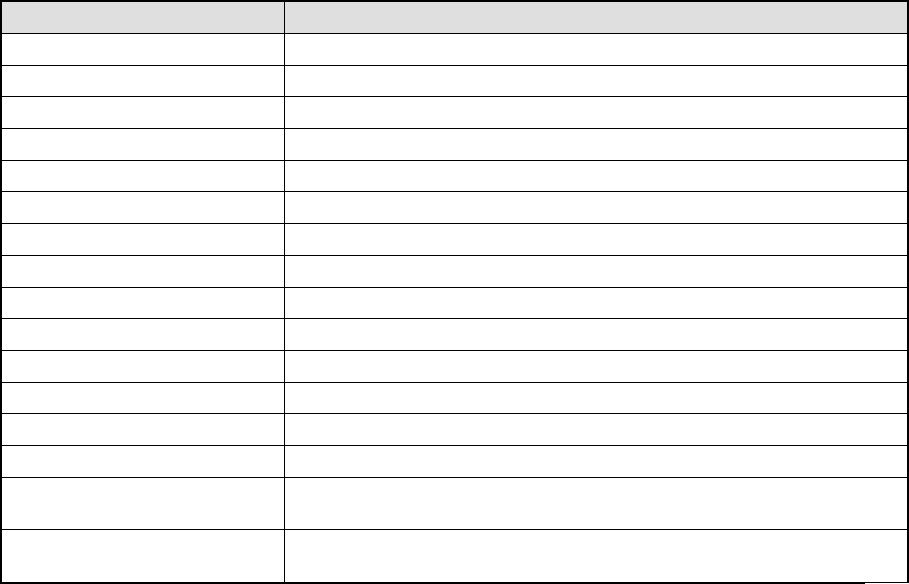
(4) Check when inputting data to a production program
At data input, perform the check operation which does not make you take
consideration into the line configuration: note that you have to know the model
name to specify the station.
Classification Error
PWB data A circuit lies off the edge of a board.
PWB data BOC mark out of range error
PWB data Bad mark out of range error
Placement data Component ID duplication
Placement data/PWB data Check to see if a placement point lies off a board or circuit.
Placement data IC mark out of range error
Placement data Number of mark data records check
Component data Component type and centering method coherence check
Component data Placement/coating coherence check
Component data/Pick data Component height range check by the station type
Pick data Package duplication check
Pick data Check of the number of registered tray holders *1
Pick data Lane number and stick type coherence check
Pick data Tray holder type consistency check *1
Vision data
Coherence check between the component type and the number of
leads/lead position
*1
Vision data
Component dimensions check and element data/control data
coherence check
*1: Items applicable to machines other than a KE-2010