KE2010.Instruction Manual.Ver.2.01,Rev.08.pdf - 第260页
4 – 153 • If an er ror is detect ed W hen y ou click t he <OK> butt on if any error is detected, t he message appear s on the screen which asks you whether to display the descriptions of the error(s). W hen y ou cl…
4 – 152
4.9.2.1 Start up
To invoke the [Data coherence] command, select it on the Data menu.
You cannot execute the [Line coherence check] command if you do not specify any
file name.
If you execute this command although you do not specify any file name, the “Give
file name and save” dialog box appears on the screen (see Section 4.2.4 “Save As”
for details).
Specify a file name, and click the <OK> button. The system starts the line
coherence check.
When you click the <Cancel> button, the system stops the process for saving a file
with the specified file name. Therefore, any file is not specified, and the system
cannot execute the line coherence check.
Note that the “Give file name and save” dialog box that appears when the line
coherence check starts up does not allow you to save the file in the format
applicable to other model unlike the dialog box that appears when you save a file
normally.
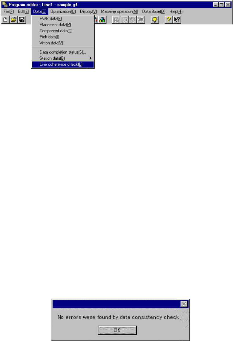
4.9.2.2 Reporting the check result
The message box appears on the screen which indicates whether an error occurs or
not and displays the number of errors if any.
• If any error is not detected
4 – 153
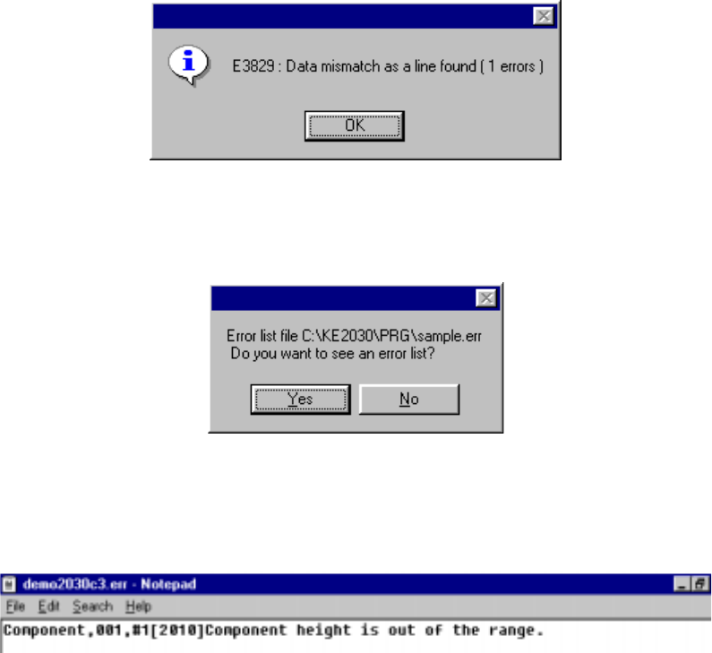
• If an error is detected
When you click the <OK> button if any error is detected, the message appears
on the screen which asks you whether to display the descriptions of the error(s).
When you click the <OK> button, the error lists appears with the Notepad,
which is bundled with Windows.
The error lists displays the data type, data number, error item name, and cause
of the error detected in this order.
4 – 154
4.10 Optimization
(1) Outline
The Optimization utility optimizes the feeder mounting position and the
pick-up/placement order of a production program which was created with the
Program Editing utility.
The optimization output result is affected by the factors described in the following
table:
Table 4.10.1 Optimization Factors
Factor Detailed Factor
Machine Setup settings Station types
Used status of each unit
Production Program data Nozzles to be used
Feeders to be used
Number of component reels available to production
Centering method
(2) Types of Optimization Paths
Optimization consists of the “Execution Path” described in the table below. Each
execution path is loop-processed by the “Feedback” option.
Table 4.10.2 Execution Paths
Path Function Description
Feeder Layout Outputs the optimum feeder mounting position to the program data that was divided
to each station.
Re-arrange
Placement Order
Outputs the optimal pick and placement order according to the feeder layout output.
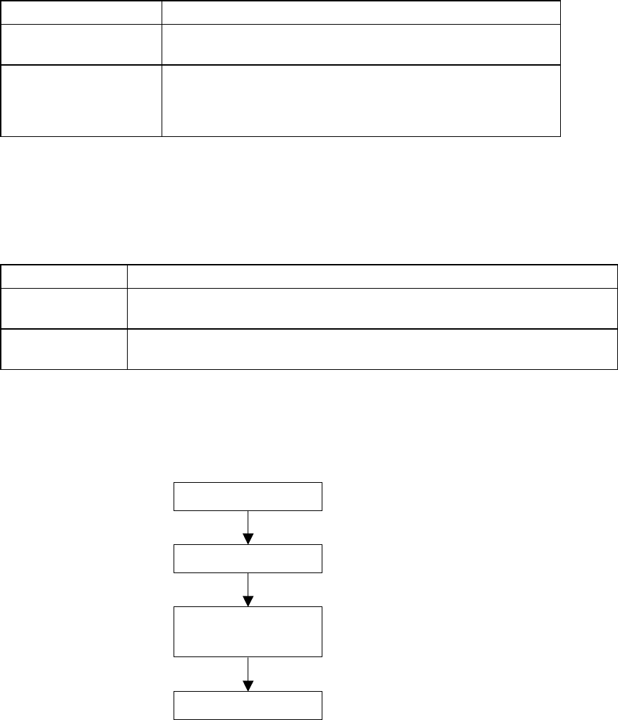
(3) Optimization Flow and Production Program File
Figure 4.10.1 Optimization Flow and Production Program File
Optimization flow
Start of optimization
Feeder layout
Rearrangement of
placement order
End of optimization