KE2010.Instruction Manual.Ver.2.01,Rev.08.pdf - 第261页
4 – 154 4.10 Optimization (1) Outli ne The Opt imization utility optimizes the f eeder m ounting position and the pick-up/ placement order of a pr oduction progr am which was created with the Progr am Editing utilit y . …
4 – 153
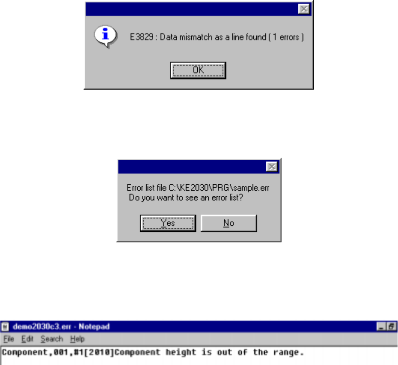
• If an error is detected
When you click the <OK> button if any error is detected, the message appears
on the screen which asks you whether to display the descriptions of the error(s).
When you click the <OK> button, the error lists appears with the Notepad,
which is bundled with Windows.
The error lists displays the data type, data number, error item name, and cause
of the error detected in this order.
4 – 154
4.10 Optimization
(1) Outline
The Optimization utility optimizes the feeder mounting position and the
pick-up/placement order of a production program which was created with the
Program Editing utility.
The optimization output result is affected by the factors described in the following
table:
Table 4.10.1 Optimization Factors
Factor Detailed Factor
Machine Setup settings Station types
Used status of each unit
Production Program data Nozzles to be used
Feeders to be used
Number of component reels available to production
Centering method
(2) Types of Optimization Paths
Optimization consists of the “Execution Path” described in the table below. Each
execution path is loop-processed by the “Feedback” option.
Table 4.10.2 Execution Paths
Path Function Description
Feeder Layout Outputs the optimum feeder mounting position to the program data that was divided
to each station.
Re-arrange
Placement Order
Outputs the optimal pick and placement order according to the feeder layout output.
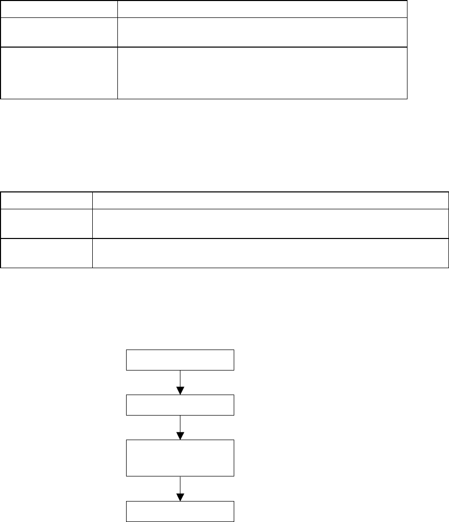
(3) Optimization Flow and Production Program File
Figure 4.10.1 Optimization Flow and Production Program File
Optimization flow
Start of optimization
Feeder layout
Rearrangement of
placement order
End of optimization
4 – 155
(4) Layer priorities
Priorities are given to each layer as follows:
Placement layers > Component layers > Component types and heights* >
smaller nozzle sizes*
*: Only when the options are enabled.
Example:
Table 4.10.3 Layer priorities
Placement
layer
Component
layer
Component
types&heights
(option)
Smaller nozzle
size (option)
Higher
1 1 1 501
3 4 3 503
4 4 4 502
6 3 1 504
Lower
7 7 7 508
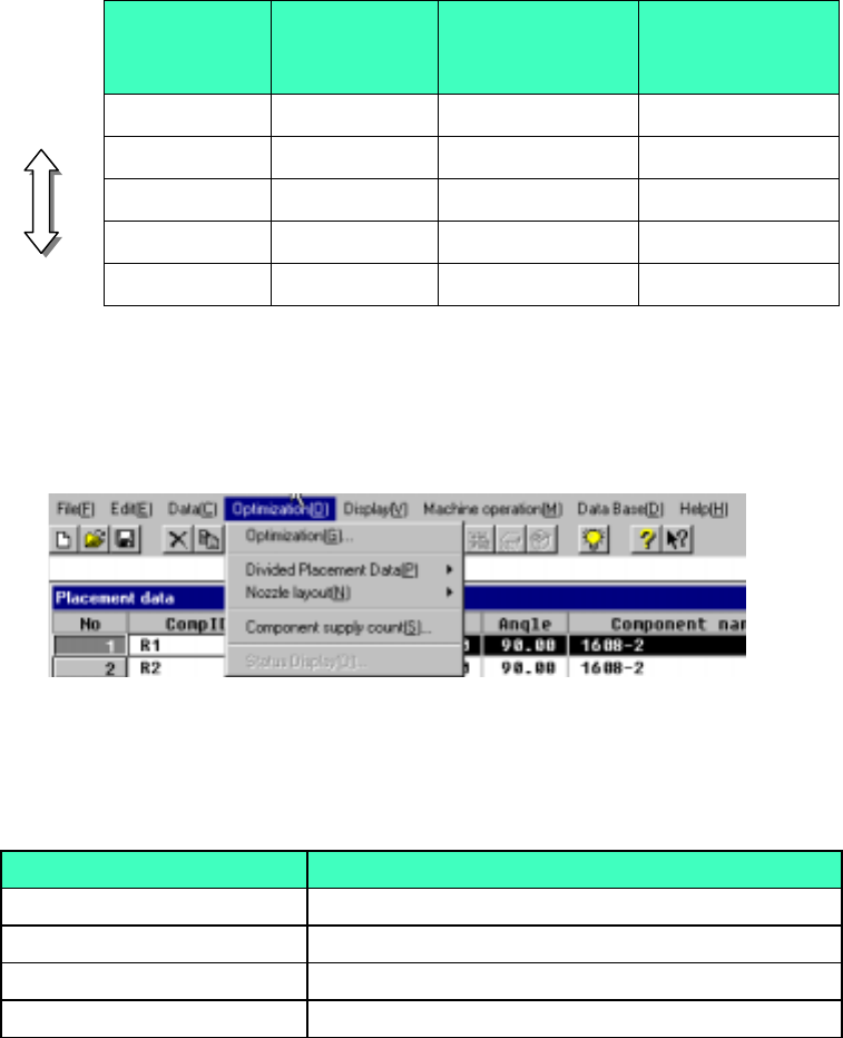
(5) Optimization Menu Organization
The Optimization menu is organized as shown below:
Figure 4.10.2 Optimization Menu Organization
Table 4.10.4 Optimization Menu Items and Their Descriptions
Item Descriptions
Optimization (G) Sets optimization options and executes optimization
Divided Placement Data (P) Displays placement data distributed to each station
Nozzle layout(N) Displays nozzle information distributed to each station
Component supply count (S) Sets the number of reels for each component type