KE2010.Instruction Manual.Ver.2.01,Rev.08.pdf - 第282页
4 – 175 4.11 Display ① Component for m and Component list If you invoke these comm ands when Component data appears on the scr een, they changes the Com ponent data display method: for m or list. See the Section on the b…
4 – 174
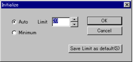
(2) Initializing the “Component supply count” setting
The <Initialize> button sets the “Component supply count” automatically or sets it
to the minimum number. When you click the <Initialize> button, the following
dialog box appears on the screen.
When you select the “Auto” radio button, you can set the upper limit of
“Component supply count” in the "Limit firld".
The default value is 20.
Figure 4.10.4.6 Example for manually setting the number of components to be supplied
• Auto Initializes each “Component supply count” automatically
in the same manner as the “Auto” radio button selection
does on the Change supply dialog box.
• Minimum Initializes each “Component supply count” to the total
number of the corresponding components in Pick data.
• OK Your change will take effect on the Component Supply
Count dialog box.
• Cancel Cancels your change.
• Save Limit as default: The system registers the upper limit value as the default
value. This value is used to create a new program by
default.
(3) OK
Saves the settings and closes the Component supply count dialog box.
(4) Cancel
Cancels the settings and closes the Component supply count dialog.
4 – 175
4.11 Display
① Component form and Component list
If you invoke these commands when Component data appears on the screen, they
changes the Component data display method: form or list. See the Section on
the basic operations of Component data.
② Vision Form and Vision List
See Section 5.2.2 “Basic operation” of Chapter 5 “VCS”.
③ Feeder layout
See the Section on the feeder layout.
④ Tool bar
This command displays or hides the tool bar on the screen.
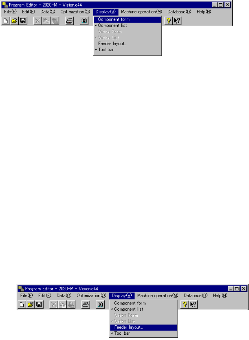
4.11.1 Feeder layout
When you select the [Feeder layout] command on the Display (V) menu, it
graphically displays the feeder layout per each station according to the list of Pick
data. Mounting or not mounting of each feeder is displayed to allow you to know it
easily.
Figure 4.11.1.1 Selecting the [Feeder layout] command
4 – 176
1. Feeder layout window
An example of the feeder layout window is shown below.
Figure 4.11.1.2 Example of the Feeder layout window
Note: On the Feeder layout window, displayed are various feeders and trays whose
component feeding positions are specified in Pick data List screen. Feeders
and trays whose “Tray Feeder” or “Sply” item is set to “Auto” are not displayed
on this window.
When you click the <Close> button on the Feeder layout window, this window
closes.
When you press the ALT and F4 keys of the keyboard at the same time, this
window closes also.
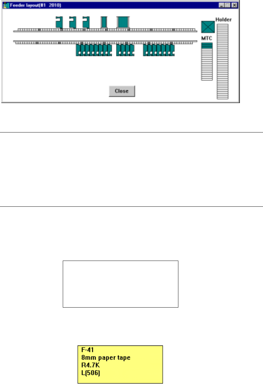
(1) When you move the cursor over the figure of a feeder on the Feeder layout
window with a trackball, part of the Component data associated with the feeder
appears on the screen as a pop-up menu.
Feeder mounting position
Feeder type
Component name
Centering method (nozzle number)
Lane number
Figure 4.11.1.3 General format of component data pop-up menu
Figure 4.11.1.4 Component data pop-up menu (for a feeder)