KE2010.Instruction Manual.Ver.2.01,Rev.08.pdf - 第298页
4 – 191 The operat ion flow in each mode is shown below . Figure 4.12.2.1. 1 Operation flow in Single Measurement mode Figure 4.12.2.1. 2 Operation flow in Continuous Measurement mode Re-meas urem ent Start of current co…
4 – 190
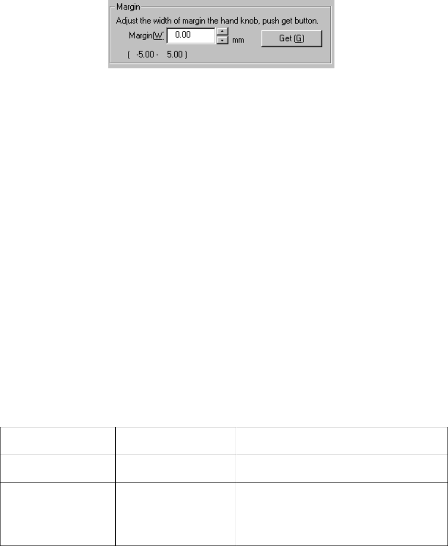
3) Margin
① Margin (W)
Use the spin button or enter a number from a keyboard to set the margin
between a PWB and the PWB transport rails.
② <Get> button
This button subtracts the PWB dimension (Y) from the current width of the
PWB transport rails, and sets the result as the margin. Use the knob located
on the front of the main unit to adjust the PWB transport rails width before
clicking this button.
4) <Conveyor> button
This button invokes the Conveyor dialog box.
5) Origin width
This button zeroes the automatic PWB width adjustment device.
6) <Apply> button
This button applies the value set as the margin to the production conditions.
To quit this dialog box, click the <Exit> button.
4.12.2 Measurement
This command allows a component to be attached on actually to measure it with each
hardware device, then loads the measured result to a production program.
4.12.2.1 Measurement mode
Two types of modes are provided for measurement operation: “Continuous
Measurement” and “Single Measurement”. To switch mode, select the
corresponding command.
The command and its corresponding measurement mode are shown in Table below:
Table 4.12.2.1 Measurement mode and its corresponding menu command
Command on the
Measurement sub-menu
Measurement mode Description
Current component Single Measurement Measures a component displayed on the
Component form screen.
All component Continuous Measurement Measures all components/components which
satisfy the conditions specified in a production
program. In Single Measurement mode, you can
measure a component which failed to be measured
for some reason individually.
4 – 191
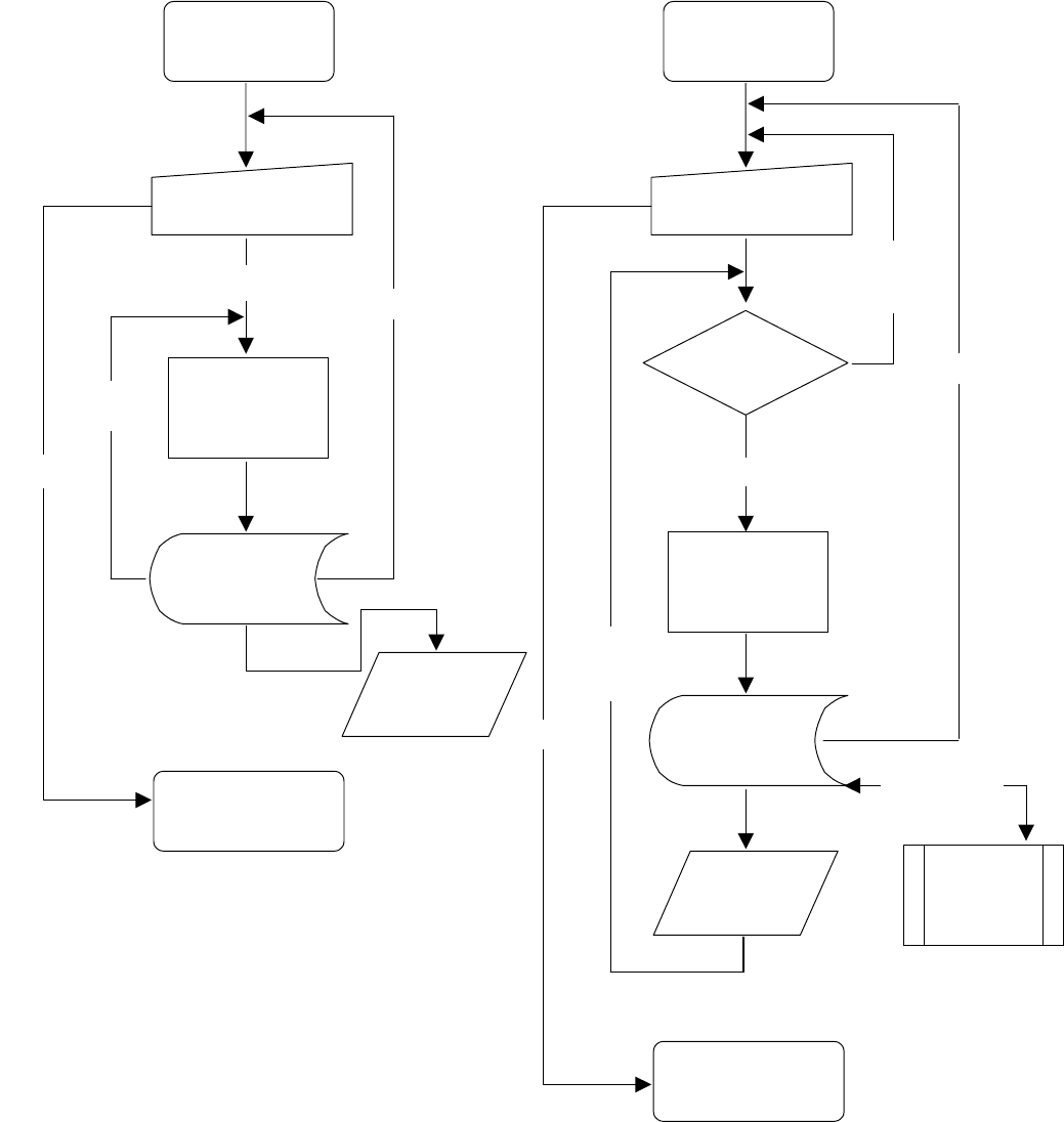
The operation flow in each mode is shown below.
Figure 4.12.2.1.1 Operation flow in
Single Measurement mode
Figure 4.12.2.1.2 Operation flow in
Continuous Measurement mode
Re-measurem
ent
Start of current
component
measurement
Setting of the conditions
(in the dialog box)
Measurement
Display of the
result
(in the dialog box)
End of the current
component
measurement
Saving the result
into a production
program.
Start of measurement
Abort
End
Measurement
of the next
component
Start of continuous
measurement
Setting of the conditions
(in the dialog box)
Measurement
Display of the
result (in the
dialog box)
End of Continuous
Measurement
Saving the result
into a production
program.
Any component
to be measured ?
Single
Measurement
No component
to be
measured
Yes
End
Abort
Detailed
measurement
4 – 192
4.12.2.2 Measurement type
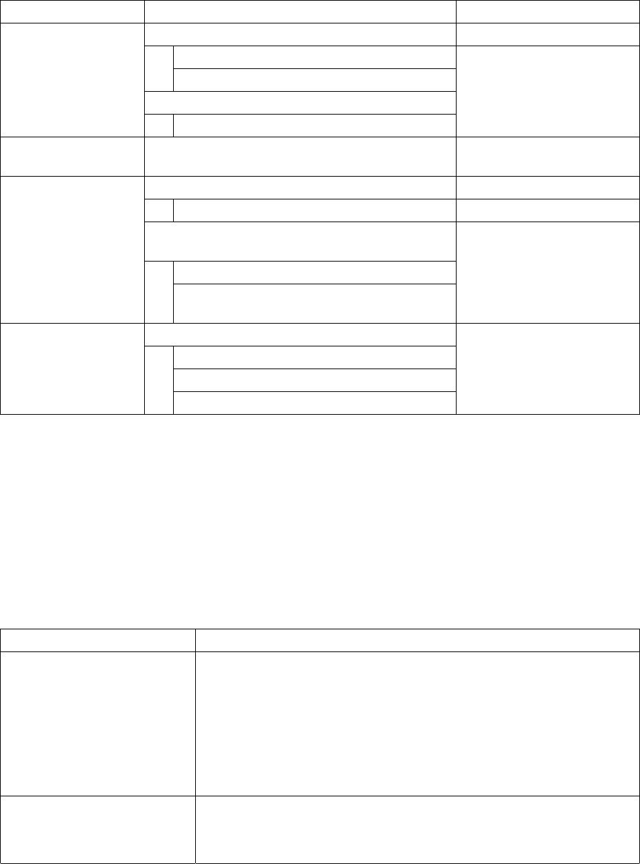
The items to be measured are outlined in the table below.
Table 4.12.2.2 Outline of the measurement items
Measurement item Description Remarks
Measures the dimensions of a component.
Width
Length
Automatically calculates the optimal nozzle number.
Dimensions of a
component (length
and width)
Nozzle number
Pick-up vacuum
pressure
Measures the vacuum pressure used to pick up a
component.
Measures the height of a component.
Height of a component
Automatically calculates the optimum values set for
laser centering.
Laser height
Height of a component
Value used for judging if a component is placed
on its side (if a tombstone error occurs).
Available to a component
centered with laser only.
Measures the dimensions of a lead.
Lead pitch
Lead length
Dimensions of a lead
Number of leads/missing lead information
Available to a component
centered with the VCS only.
4.12.2.2.1 Function of each measurement item
① Component dimensions measurement function
This function measures the width and length of a component with laser or the VCS
depending on the centering method of a component to be measured. At the
same time, the optimum nozzle number is automatically calculated also. The
measurement methods are shown in Table below.
Table 4.12.2.2.1.1 Component dimensions measurement methods
Component to be measured Method
Component which is to be
recognized with laser
1. Obtain the angle of the current component with laser.
↓
2. Rotate a component to 0 degrees in the theta direction so that the width
of laser can be the horizontal dimension.
↓
3. Rotate a component to 90 degrees in the theta direction so that the
width of laser can be the vertical dimension.
Component which is to be
recognized with the VCS
1. Recognize a component with the VCS to obtain its dimensions.
↓
2. Set the responded values to the width and length of a component.