KE2010.Instruction Manual.Ver.2.01,Rev.08.pdf - 第299页
4 – 192 4.12.2.2 Measurement type The item s to be measured ar e outlined in the t able below . T able 4.12.2.2 Outline of the measurement items Measurement item Description Remarks Measures the dimensions of a component…
4 – 191
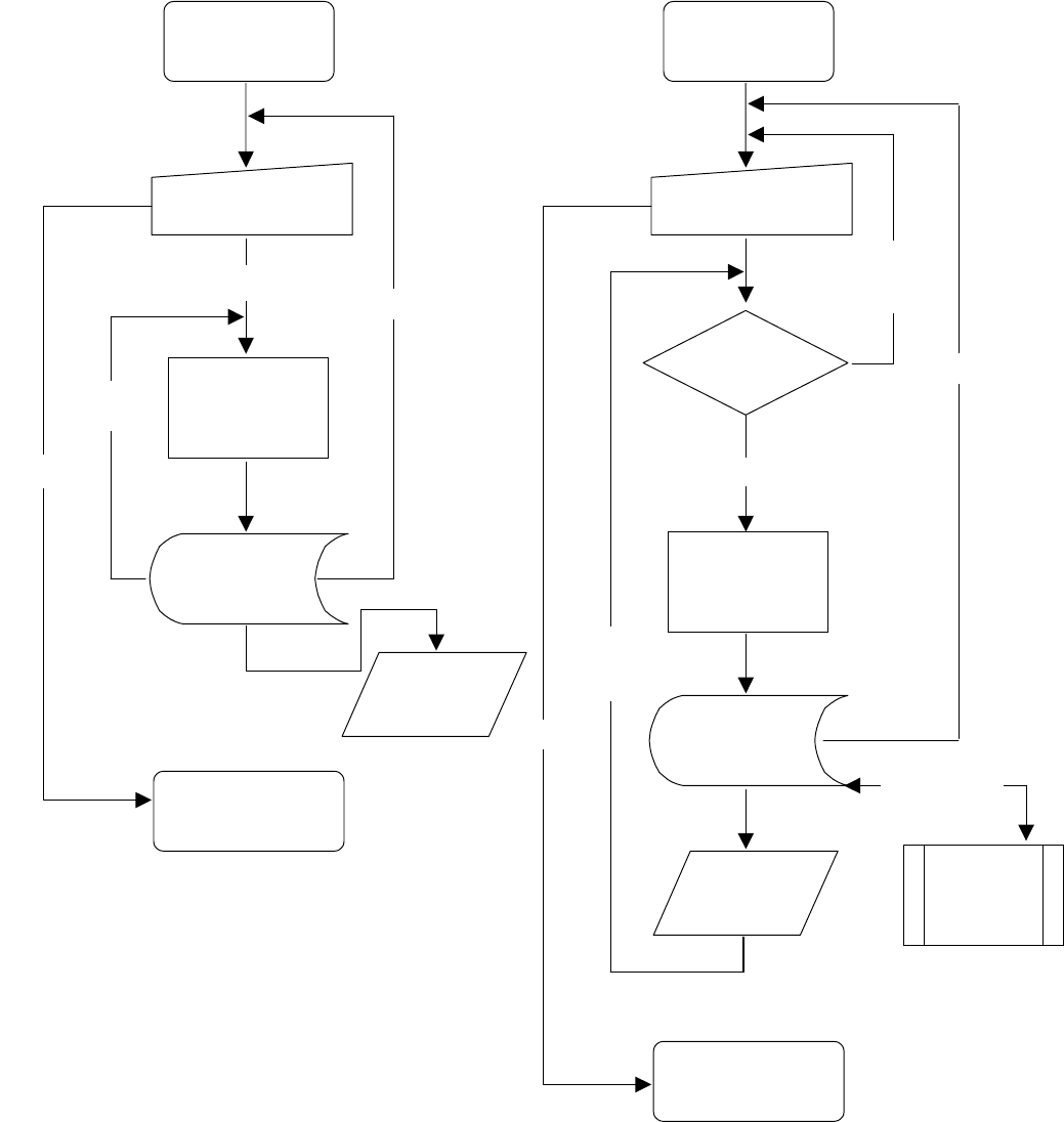
The operation flow in each mode is shown below.
Figure 4.12.2.1.1 Operation flow in
Single Measurement mode
Figure 4.12.2.1.2 Operation flow in
Continuous Measurement mode
Re-measurem
ent
Start of current
component
measurement
Setting of the conditions
(in the dialog box)
Measurement
Display of the
result
(in the dialog box)
End of the current
component
measurement
Saving the result
into a production
program.
Start of measurement
Abort
End
Measurement
of the next
component
Start of continuous
measurement
Setting of the conditions
(in the dialog box)
Measurement
Display of the
result (in the
dialog box)
End of Continuous
Measurement
Saving the result
into a production
program.
Any component
to be measured ?
Single
Measurement
No component
to be
measured
Yes
End
Abort
Detailed
measurement
4 – 192
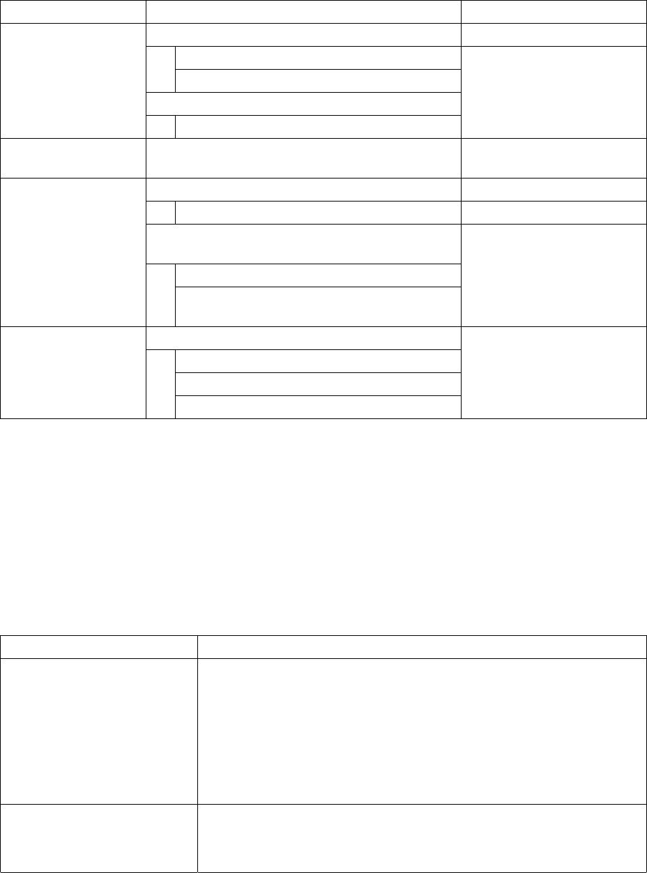
4.12.2.2 Measurement type
The items to be measured are outlined in the table below.
Table 4.12.2.2 Outline of the measurement items
Measurement item Description Remarks
Measures the dimensions of a component.
Width
Length
Automatically calculates the optimal nozzle number.
Dimensions of a
component (length
and width)
Nozzle number
Pick-up vacuum
pressure
Measures the vacuum pressure used to pick up a
component.
Measures the height of a component.
Height of a component
Automatically calculates the optimum values set for
laser centering.
Laser height
Height of a component
Value used for judging if a component is placed
on its side (if a tombstone error occurs).
Available to a component
centered with laser only.
Measures the dimensions of a lead.
Lead pitch
Lead length
Dimensions of a lead
Number of leads/missing lead information
Available to a component
centered with the VCS only.
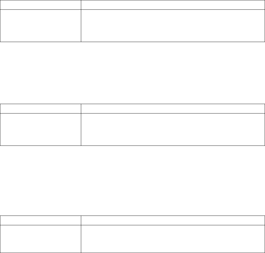
4.12.2.2.1 Function of each measurement item
① Component dimensions measurement function
This function measures the width and length of a component with laser or the VCS
depending on the centering method of a component to be measured. At the
same time, the optimum nozzle number is automatically calculated also. The
measurement methods are shown in Table below.
Table 4.12.2.2.1.1 Component dimensions measurement methods
Component to be measured Method
Component which is to be
recognized with laser
1. Obtain the angle of the current component with laser.
↓
2. Rotate a component to 0 degrees in the theta direction so that the width
of laser can be the horizontal dimension.
↓
3. Rotate a component to 90 degrees in the theta direction so that the
width of laser can be the vertical dimension.
Component which is to be
recognized with the VCS
1. Recognize a component with the VCS to obtain its dimensions.
↓
2. Set the responded values to the width and length of a component.
4 – 193
② Component height measuring function
This function measures the height of a component with laser. At the same time,
the system automatically calculates the optimum laser height and the value to be
used for judging if a chip is placed on its side (if a tombstone error occurs). The
measurement method is described in Table below.
Table 4.12.2.2.1.2 Component height measurement method
Component to be measured Method
Component which is to be
recognized with laser
Component which is to be
recognized with the VCS
1. Move up and down a component.
↓
2. Handle the shade of a component as the height of a component.
③ Component vacuum pressure measuring function
This function measures the vacuum pressure used to pick up a component. The
measurement method is described in Table below.
Table 4.12.2.2.1.3 Component vacuum pressure measurement method
Component to be measured Method
Component which is to be
recognized with laser
Component which is to be
recognized with the VCS
1. Pick up a component and obtain the head vacuum pressure level.
↓
2. Set the obtained value as the head vacuum level.
④ Lead information measuring function
This function obtains the lead information with the VCS, and it is available to only a
component which is to be centered with the VCS. The measurement method is
described in Table below.
Table 4.12.2.2.1.4 Lead information obtaining method
Component to be measured Method
Component to be recognized
with the VCS
1. Recognize a component with the VCS to obtain the lead information.
↓
2. Set the obtained values as the lead dimensions.