KE2010.Instruction Manual.Ver.2.01,Rev.08.pdf - 第300页
4 – 193 ② Component height m easuring f unction This f unct ion measures the heig ht of a component with laser . At the same t ime, the system autom atically calculates the optim um laser heig ht and the value to be used…
4 – 192
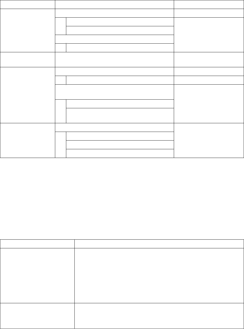
4.12.2.2 Measurement type
The items to be measured are outlined in the table below.
Table 4.12.2.2 Outline of the measurement items
Measurement item Description Remarks
Measures the dimensions of a component.
Width
Length
Automatically calculates the optimal nozzle number.
Dimensions of a
component (length
and width)
Nozzle number
Pick-up vacuum
pressure
Measures the vacuum pressure used to pick up a
component.
Measures the height of a component.
Height of a component
Automatically calculates the optimum values set for
laser centering.
Laser height
Height of a component
Value used for judging if a component is placed
on its side (if a tombstone error occurs).
Available to a component
centered with laser only.
Measures the dimensions of a lead.
Lead pitch
Lead length
Dimensions of a lead
Number of leads/missing lead information
Available to a component
centered with the VCS only.
4.12.2.2.1 Function of each measurement item
① Component dimensions measurement function
This function measures the width and length of a component with laser or the VCS
depending on the centering method of a component to be measured. At the
same time, the optimum nozzle number is automatically calculated also. The
measurement methods are shown in Table below.
Table 4.12.2.2.1.1 Component dimensions measurement methods
Component to be measured Method
Component which is to be
recognized with laser
1. Obtain the angle of the current component with laser.
↓
2. Rotate a component to 0 degrees in the theta direction so that the width
of laser can be the horizontal dimension.
↓
3. Rotate a component to 90 degrees in the theta direction so that the
width of laser can be the vertical dimension.
Component which is to be
recognized with the VCS
1. Recognize a component with the VCS to obtain its dimensions.
↓
2. Set the responded values to the width and length of a component.
4 – 193
② Component height measuring function
This function measures the height of a component with laser. At the same time,
the system automatically calculates the optimum laser height and the value to be
used for judging if a chip is placed on its side (if a tombstone error occurs). The
measurement method is described in Table below.
Table 4.12.2.2.1.2 Component height measurement method
Component to be measured Method
Component which is to be
recognized with laser
Component which is to be
recognized with the VCS
1. Move up and down a component.
↓
2. Handle the shade of a component as the height of a component.
③ Component vacuum pressure measuring function
This function measures the vacuum pressure used to pick up a component. The
measurement method is described in Table below.
Table 4.12.2.2.1.3 Component vacuum pressure measurement method
Component to be measured Method
Component which is to be
recognized with laser
Component which is to be
recognized with the VCS
1. Pick up a component and obtain the head vacuum pressure level.
↓
2. Set the obtained value as the head vacuum level.
④ Lead information measuring function
This function obtains the lead information with the VCS, and it is available to only a
component which is to be centered with the VCS. The measurement method is
described in Table below.
Table 4.12.2.2.1.4 Lead information obtaining method
Component to be measured Method
Component to be recognized
with the VCS
1. Recognize a component with the VCS to obtain the lead information.
↓
2. Set the obtained values as the lead dimensions.
4 – 194
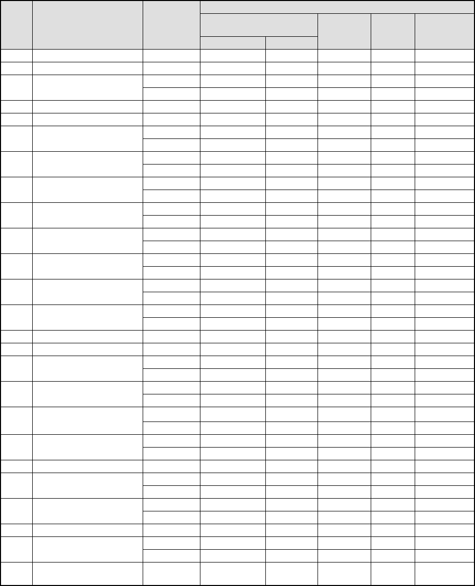
4.12.2.2.2 Measurement restrictions imposed depending on the component type
The measurement items are restricted depending on the component type of
Component data as shown in Table below.
Table 4.12.2.2.2 Measurement items available depending on the component type
Measurement items
Dimensions of a
component
No. Component type
Centering
method
Length/width Height
Pick-up
vacuum
pressure
Laser
height
Lead
information
1 Square chip Laser
○
○
○
○
2 MELF Laser
○
○
○
○
Laser
○
○
○
3
Aluminum electrolytic
capacitor
VCS
○
○
4 GaAsFET Laser
○
○
○
5 SOT Laser
○
○
○
○
Laser
○
*3
○
○
○
○
*3 6 SOP
VCS
○
*1
○
○
○
*1
Laser
○
○
○
7 SOJ
VCS
○
○
Laser
○
*3
○
○
○
○
*3 8 QFP
VCS
○
*1
○
○
○
*1
Laser
○
○
○
9 PLCC (QFJ)
VCS
○
○
Laser
○
*3
○
○
○
○
*3 10 PQFP (BQFP)
VCS
○
*1
○
○
○
*1
Laser
○
*3
○
○
○
○
*3 11 TSOP
VCS
○
*1
○
○
○
*1
Laser
○
*3
○
○
○
○
*3 12 TSOP2
VCS
○
*1
○
○
○
*1
Laser
○
○
○
13 BGA
VCS
○
○
14 Network resistor Laser
○
○
○
15 Trimmer Laser
○
○
○
Laser
○
○
○
○
*2, *3 16
Unidirectional lead
connector
VCS
○
○
○
*1, *2
Laser
○
○
○
17 J lead socket
VCS
○
○
Laser
○
○
○
18 Gull-wing socket
VCS
○
○
Laser
○
○
○
19 Socket with a bumper
VCS
○
○
20 Other components Laser
○
○
○
Laser
○
*3
○
○
○
○
*2, *3 21
Bidirectional lead
connector
VCS
○
*1
○
○
○
*1, *2
Laser
○
*3
○
○
○
22 SOP with a heat sink
VCS
○
*1
○
○
23 FBGA Laser
○
○
○
Laser
○
○
○
24 Z lead connector
VCS
○
○
25
Extension-lead
connector
VCS
○
○
*1 Only components which have seven or more leads
(The dimensions of a component are 50 mm x 50 mm or less.)
*2 The parts configured with the same shape of leads and without any arm or metal fitting at both ends.
*3 Measured with the VCS device.