KE2010.Instruction Manual.Ver.2.01,Rev.08.pdf - 第302页
4 – 195 4.12.2.3 A ctions t aken during measurement ① Head used to pick up a component The system automatically selects a head used t o pick up a component so that a nozzle can be replaced w ith another one lest f requen…

4 – 194
4.12.2.2.2 Measurement restrictions imposed depending on the component type
The measurement items are restricted depending on the component type of
Component data as shown in Table below.
Table 4.12.2.2.2 Measurement items available depending on the component type
Measurement items
Dimensions of a
component
No. Component type
Centering
method
Length/width Height
Pick-up
vacuum
pressure
Laser
height
Lead
information
1 Square chip Laser
○
○
○
○
2 MELF Laser
○
○
○
○
Laser
○
○
○
3
Aluminum electrolytic
capacitor
VCS
○
○
4 GaAsFET Laser
○
○
○
5 SOT Laser
○
○
○
○
Laser
○
*3
○
○
○
○
*3 6 SOP
VCS
○
*1
○
○
○
*1
Laser
○
○
○
7 SOJ
VCS
○
○
Laser
○
*3
○
○
○
○
*3 8 QFP
VCS
○
*1
○
○
○
*1
Laser
○
○
○
9 PLCC (QFJ)
VCS
○
○
Laser
○
*3
○
○
○
○
*3 10 PQFP (BQFP)
VCS
○
*1
○
○
○
*1
Laser
○
*3
○
○
○
○
*3 11 TSOP
VCS
○
*1
○
○
○
*1
Laser
○
*3
○
○
○
○
*3 12 TSOP2
VCS
○
*1
○
○
○
*1
Laser
○
○
○
13 BGA
VCS
○
○
14 Network resistor Laser
○
○
○
15 Trimmer Laser
○
○
○
Laser
○
○
○
○
*2, *3 16
Unidirectional lead
connector
VCS
○
○
○
*1, *2
Laser
○
○
○
17 J lead socket
VCS
○
○
Laser
○
○
○
18 Gull-wing socket
VCS
○
○
Laser
○
○
○
19 Socket with a bumper
VCS
○
○
20 Other components Laser
○
○
○
Laser
○
*3
○
○
○
○
*2, *3 21
Bidirectional lead
connector
VCS
○
*1
○
○
○
*1, *2
Laser
○
*3
○
○
○
22 SOP with a heat sink
VCS
○
*1
○
○
23 FBGA Laser
○
○
○
Laser
○
○
○
24 Z lead connector
VCS
○
○
25
Extension-lead
connector
VCS
○
○
*1 Only components which have seven or more leads
(The dimensions of a component are 50 mm x 50 mm or less.)
*2 The parts configured with the same shape of leads and without any arm or metal fitting at both ends.
*3 Measured with the VCS device.

4 – 195
4.12.2.3 Actions taken during measurement
① Head used to pick up a component
The system automatically selects a head used to pick up a component so that a
nozzle can be replaced with another one lest frequently by attempting to use a
nozzle already attached on a head. The system may use a different head every
time it measures a component depending on the nozzle attachment conditions.
② Return of a component after measurement
Some components are returned to the original position and other ones are
discarded after measurement depending on their packaging style as shown in
Table below. When the setting item “Compo Reject to”, indicating the component
discarding method, is set to “Trash conveyor” or “Protect”, the system discards a
component according to this setting. The place onto which the system discards a
component is based on the “Compo Reject to” setting of Component data. Since
a component whose size is 1 mm or less may be placed on its side (tombstone
error) or turned upside down when it is returned, the system asks you how to
handle it.
Table 4.12.2.3 Conditions for returning/discarding a component
Packaging
style
Condition 1 Condition 2
Returning a
component
Discarding a
component
32-mm tape feeder
○
The shorter side length of the outer
dimensions is 1 mm or less.
Query * 1
Tape
Tape feeders other
than the above
The shorter side length of the outer
dimensions is 1 mm or more.
○
○
*2
The shorter side length of the outer
dimensions is 1 mm or less.
Query * 1
Bulk
The shorter side length of the outer
dimensions is 1 mm or more.
○
○
*2
Holder
○
○
*2
MTC
○
○
*2
MTS
○
○
*2
Stick
○
*1 The system displays a dialog box which asks you whether to return a component or discard it.
In Continuous Measurement mode, the system displays such a dialog box before starting
continuous measurement operation.
*2 The system discards a component when the setting item “Compo Reject to” is set to “Trash
conveyor” or “Protect”.
③ Selecting a feeder which is used to pick up a component
If there are two ore more feeders assigned to the same type of component in Pick
data, a component starts being picked up based on the data you entered first as
the default setting. Only in Single Measurement mode, you can change a feeder
as desired.
④ Changing the coordinates of a pick-up position
If the system cannot pick up a component properly, manually enter the coordinates
or use the HOD device to teach the coordinates to change the coordinates of a
pick-up position.
⑤ Manual component pick-up
If there is no Pick data created, you can manually attach a component to the
nozzle. However, in this case, you cannot enter coordinates that indicate the
component pick-up position. You cannot operate a feeder either.
4 – 196
4.12.2.4 Measurement operation
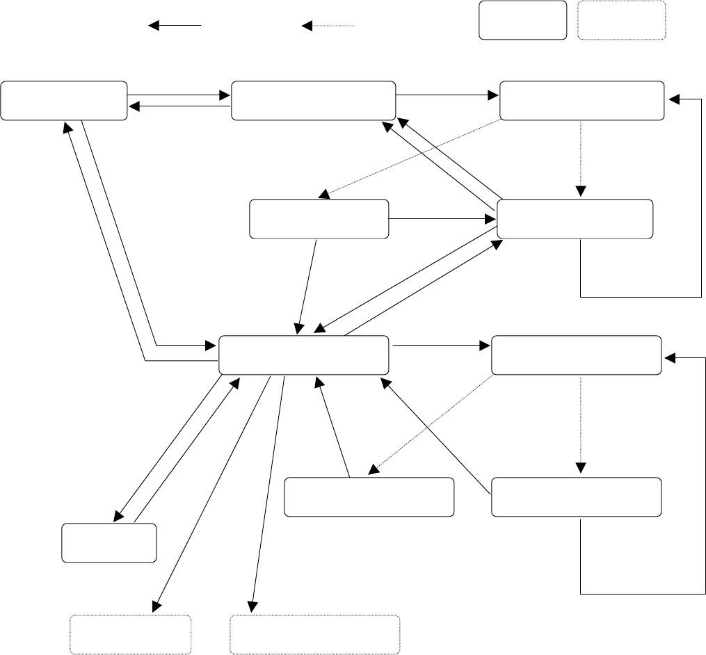
4.12.2.4.1 Transition of measurement operations
The displayed screen and machine state change as shown below in
Single/Continuous Measurement mode.
User operation Process condition
Process only
“All component”
menu
BACK
Start of continuous
measurement
“Continuation measurement”
conditions setting dialog box
“Executing continuous
measurement” dialog box
Selection of a menu
Display of a
measurement error
“Result of continuation
measurement” dialog box
“Measurement” dialog box
“Executing measurement”
dialog box
Dialog box
“Result of measurement” dialog
box
Display of measurement error
Teaching
Feeder knocking Change of a pick-up position
“Current
component”
menu
BACK
Yes
Error
STOP
STOP
Normally
Finishing
measurement of
all components
No
Single
measurement
BACK (in Continuous
Measurement mode)
START
OK/NEXT
Single
measurement
HOD device key
ENTER/CANCEL
FEED
PREV/NEXT
OK
Error
Cancel
OK
Normally
RETRY