KE2010.Instruction Manual.Ver.2.01,Rev.08.pdf - 第316页
4 – 209 3) <OK/NEX T> butt on (<ST ART> button) T his button validates t he result of measurem ent, then saves the m easured values into Component data. Then, t he system start s measuring the next component.…
4 – 208
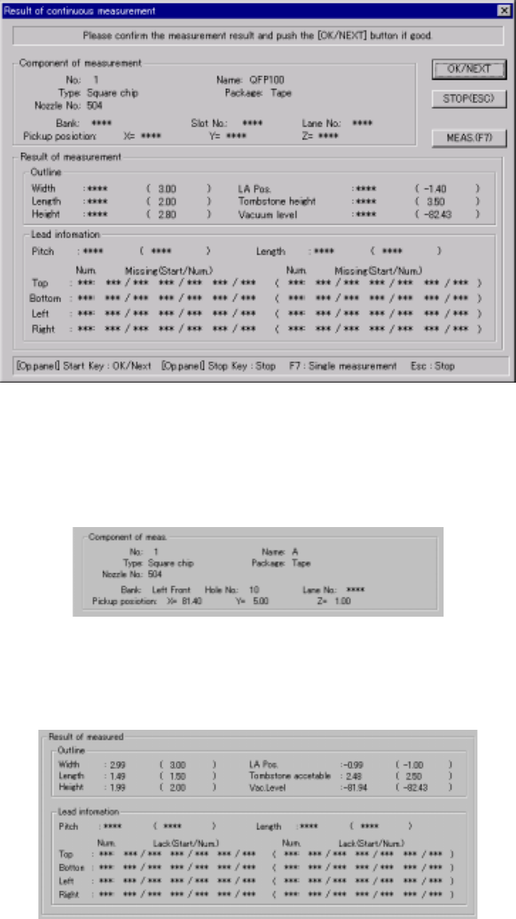
(3) “Result of continuation measurement” dialog box
When the system finishes continuous measurement completely, the following
“Result of continuation measurement” dialog box appears on the screen.
Figure 4.12.2.4.3.5 “Result of continuous measurement” dialog box
1) Component of meas. (Component of measurement)
The description of a measured component and its pick-up position are
displayed here.
2) Result of measured
The measured values are displayed here. Values specified in Component
data appear in parentheses. “***” appears in the item(s) which were not
measured.
4 – 209
3) <OK/NEXT> button (<START> button)
This button validates the result of measurement, then saves the measured
values into Component data. Then, the system starts measuring the next
component.
4) <STOP> button (ESC key)
This button cancels the result of measurement, then stops the current
continuous measurement operation to return to the previous “Continuation
measurement” dialog box.
5) <MEAS.> button (F7 key)
This button allows the system to enter Single Measurement mode.
6) Short-cut keys
On the “Result of continuation measurement” dialog box, the following
short-cut keys are provided.
Keyboard
key
Operation
panel key
HOD key Operation
START Validates the result, then measures the next
component.
ESC STOP Aborts the continuous measurement
operation.
F7 Enters Single Measurement mode.
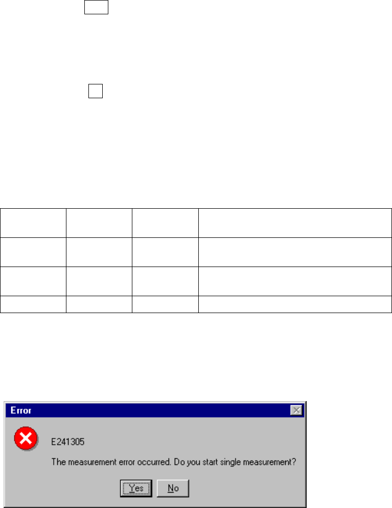
7) If a measurement error occurs
If a measurement error occurs for any reason, the following dialog box
appears on the screen to allow you to enter Single Measurement mode.
Figure 4.12.2.4.3.6 Continuous measurement error dialog box
4 – 210
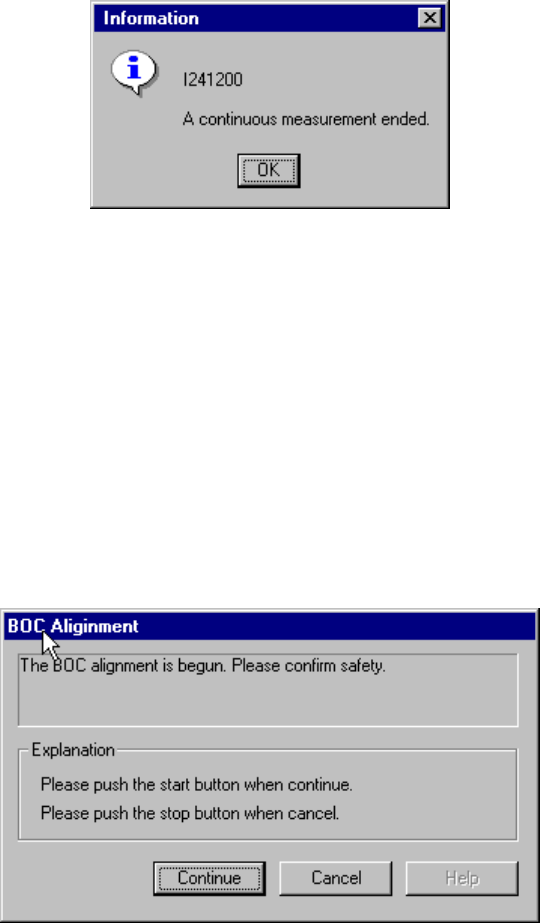
(4) When continuous measurement finishes
When the system finishes measuring all components which satisfy the specified
conditions, the following dialog box appears on the screen.
Figure 4.12.2.4.3.7 “Information” - End of continuous measurement dialog box
4.12.3 Confirmation
4.12.3.1 Mark - BOC
This command recognizes a BOC mark, then saves the measured coordinates of the
recognized BOC mark to the main unit. These measured coordinates are used to
correct coordinates during teaching of Placement data.
If the safety cover opens after you select the BOC command, the following dialog box
appears on the screen because the function to be invoked operates the axis.
Check the safety of the machine and yourself, then press the <Start> button.
Figure 4.12.3.1.1 BOC alignment - safety confirmation dialog box