KE2010.Instruction Manual.Ver.2.01,Rev.08.pdf - 第320页
4 – 213 4.12.3.2 Mark - Feeder Bank ( Front/Rear) This command r ecognizes a f eeder bank m ark, then saves the coordinates which were recognized and measured. T hese coordinates are used t o correct coor dinates during …
4 – 212
If the system fails to recognize a BOC mark, the following dialog box appears on the
screen.
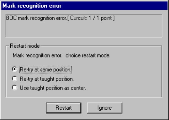
Figure 4.12.3.1.3 BOC mark recognition error dialog box
To recognize the BOC mark again, select one of the following radio buttons displayed
in the “Restart Mode” column.
① Re-try at same position.
Recognizes the BOC mark again without changing the current OCC camera
position.
② Re-try at taught position.
Recognizes the BOC mark again at the position whose coordinates were taught
with the CAMERA button of the HOD. This item is available only after you
validate the result of teaching operation.
③ Use taught position as center.
Validates the position whose coordinates were taught with the CAMERA button of
the HOD as the actual center of the recognized BOC mark. This item is
available only after you validate the result of teaching operation.
To restart the BOC mark recognition operation after selecting one of the above radio
buttons, click the <Restart> button.
When you click the <Ignore> button, the system does not recognize a BOC mark at
each circuit/board hereinafter.
4 – 213
4.12.3.2 Mark - Feeder Bank (Front/Rear)
This command recognizes a feeder bank mark, then saves the coordinates which
were recognized and measured. These coordinates are used to correct coordinates
during teaching Pick data
To recognize a mark on the front feeder bank, select the [Front] command. To
recognize a mark on the rear feeder bank, select the [Rear] command.
(When you select either of these commands with a KE-2030, marks on the left or right
station are to be recognized twice.)
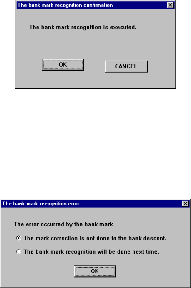
Figure 4.12.3.2.1 “The bank mark recognition confirmation” dialog box
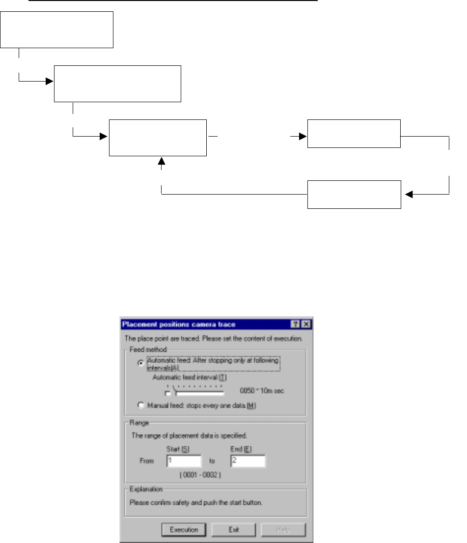
If the system fails to recognize a bank mark, the following dialog box appears on the
screen. In this case, the recognition result is not saved. Select with which timing a
mark is to be recognized.
(1) The mark correction is not done to the bank descent.: A mark is not corrected
until the bank moves down.
(2) The mark correction will be done next time: A bank mark is recognized the next
time.
Figure 4.12.3.2.2 “The bank mark recognition error” dialog box
4 – 214
4.12.3.3 Place tracking
This command allows a camera to track a component placement position. You can
see the component placement position displayed on the monitor, so you can use the
HOD to teach and edit it if the position is not appropriate. (See Chapter 6
“PRODUCTION PROCEDURES” for tracking during production.)
Operation flow for tracking a component placement position.
(1) Setting the tacking conditions
When you select the [Place tracking] command on the menu sequentially invoked
from the Machine Operation menu provided with the Program Editing utility, the
following “Placement position camera trace” dialog box appears.
Figure 4.12.3.3.1 “Placement position camera trace” dialog box
Selecting the [Place
tracking] command on the
Machine operation menu
Setting the conditions for
tracking a component placement
position with a camera
Tracking a component
placement position with
a camera
Checking coordinates
on the monitor.
Teaching with the HOD
Select
<Execution> button
Change of each set of coordinates take effect.
Move to each set
of coordinates
specified in
Placement data.
Modify each set
of coordinates.