KE2010.Instruction Manual.Ver.2.01,Rev.08.pdf - 第321页
4 – 214 4.12.3.3 Pl ace tracking This command allows a camera t o track a component placem ent position. Y ou can see the component placem ent position displayed on the monit or , so you can use the HOD to teach and edit…
4 – 213
4.12.3.2 Mark - Feeder Bank (Front/Rear)
This command recognizes a feeder bank mark, then saves the coordinates which
were recognized and measured. These coordinates are used to correct coordinates
during teaching Pick data
To recognize a mark on the front feeder bank, select the [Front] command. To
recognize a mark on the rear feeder bank, select the [Rear] command.
(When you select either of these commands with a KE-2030, marks on the left or right
station are to be recognized twice.)
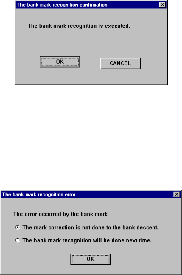
Figure 4.12.3.2.1 “The bank mark recognition confirmation” dialog box
If the system fails to recognize a bank mark, the following dialog box appears on the
screen. In this case, the recognition result is not saved. Select with which timing a
mark is to be recognized.
(1) The mark correction is not done to the bank descent.: A mark is not corrected
until the bank moves down.
(2) The mark correction will be done next time: A bank mark is recognized the next
time.
Figure 4.12.3.2.2 “The bank mark recognition error” dialog box
4 – 214
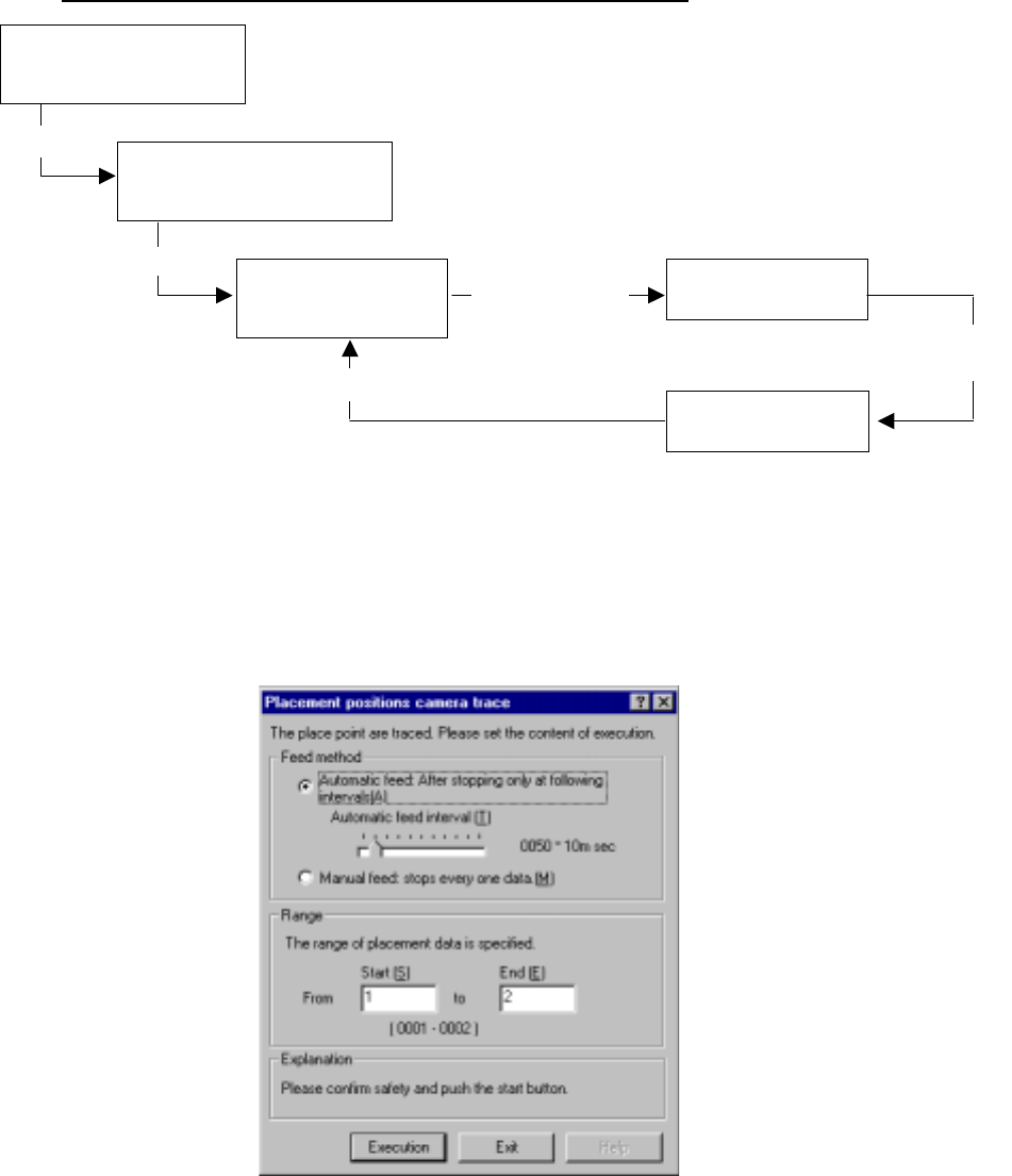
4.12.3.3 Place tracking
This command allows a camera to track a component placement position. You can
see the component placement position displayed on the monitor, so you can use the
HOD to teach and edit it if the position is not appropriate. (See Chapter 6
“PRODUCTION PROCEDURES” for tracking during production.)
Operation flow for tracking a component placement position.
(1) Setting the tacking conditions
When you select the [Place tracking] command on the menu sequentially invoked
from the Machine Operation menu provided with the Program Editing utility, the
following “Placement position camera trace” dialog box appears.
Figure 4.12.3.3.1 “Placement position camera trace” dialog box
Selecting the [Place
tracking] command on the
Machine operation menu
Setting the conditions for
tracking a component placement
position with a camera
Tracking a component
placement position with
a camera
Checking coordinates
on the monitor.
Teaching with the HOD
Select
<Execution> button
Change of each set of coordinates take effect.
Move to each set
of coordinates
specified in
Placement data.
Modify each set
of coordinates.
4 – 215
1) Feed method
① Automatic feed
The camera shoots a component placement position one by one at
regular intervals. The camera stops for the time of period specified with
the “Automatic feed interval” slider bar displayed below, then moves to
the next position.
(Automatic feed interval)
Use this slider bar to
adjust the stop time
within the range from 10
msec to five seconds.
② Manual feed
The camera stops without moving to the next position until an operator
operates it.
2) Range
Enter the range of Placement data used for tracking: from the start point to
the end point. As the
default setting, all
placement positions are to
be tracked.
After you specify the setting
items, press the <Start>
button or click the
<Execution> button.
When you click the <Exit> button, the system returns to the previous screen.
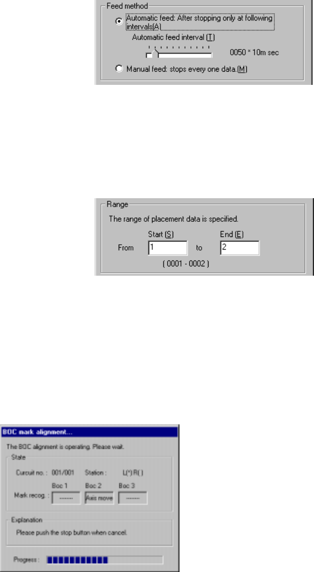
(2) Executing the BOC alignment operation
Immediately after the camera starts tracking a component placement position, the
system executes BOC alignment operation to improve the precision of the
component placement position if a production program on which a BOC mark is
set is used. (BOC marks of all circuits are to be recognized.)
Figure 4.12.3.3.2 “BOC mark alignment” dialog box