KE2010.Instruction Manual.Ver.2.01,Rev.08.pdf - 第323页
4 – 216 (3) W hile the camera is track ing a component placement posit ion After you click the <Execution> button or press the <Star t> button, the f ollowing dialog box appears on the screen while the camer …
4 – 215
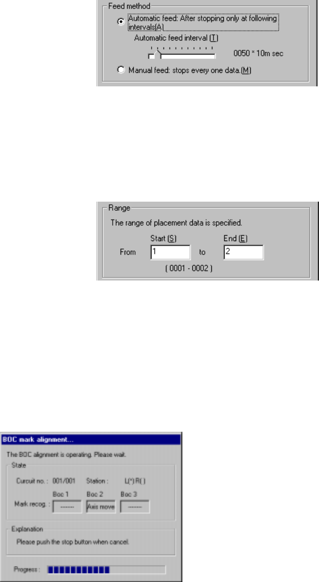
1) Feed method
① Automatic feed
The camera shoots a component placement position one by one at
regular intervals. The camera stops for the time of period specified with
the “Automatic feed interval” slider bar displayed below, then moves to
the next position.
(Automatic feed interval)
Use this slider bar to
adjust the stop time
within the range from 10
msec to five seconds.
② Manual feed
The camera stops without moving to the next position until an operator
operates it.
2) Range
Enter the range of Placement data used for tracking: from the start point to
the end point. As the
default setting, all
placement positions are to
be tracked.
After you specify the setting
items, press the <Start>
button or click the
<Execution> button.
When you click the <Exit> button, the system returns to the previous screen.
(2) Executing the BOC alignment operation
Immediately after the camera starts tracking a component placement position, the
system executes BOC alignment operation to improve the precision of the
component placement position if a production program on which a BOC mark is
set is used. (BOC marks of all circuits are to be recognized.)
Figure 4.12.3.3.2 “BOC mark alignment” dialog box
4 – 216
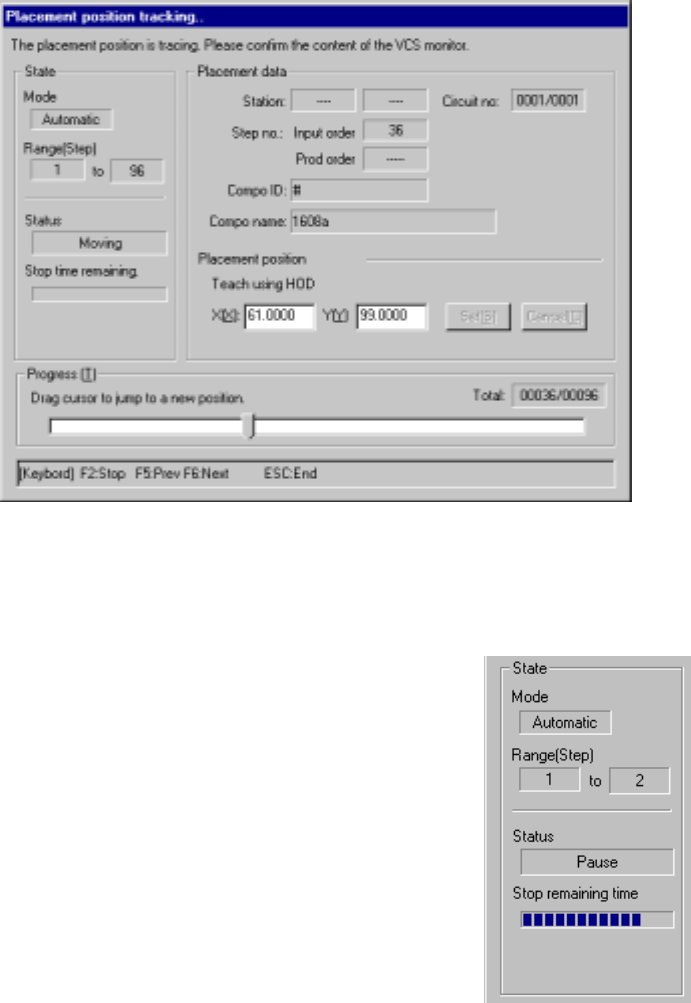
(3) While the camera is tracking a component placement position
After you click the <Execution> button or press the <Start> button, the following
dialog box appears on the screen while the camera is tracking each set of
coordinates of the component placement position.
Figure 4.12.3.3.3 “Placement position tracing” dialog box
1) State
① Mode
“Manual” or “Automatic” which is set with
the radio button “Feed method” appears
here.
② Range
When all placement points are to be
tracked, the “first” point and “end” point
are displayed here. If you change the
tracking range, the changed step
number is displayed.
③ Status
“Moving” indicates that the axis is
moving. “Pause” indicates that the axis
pauses temporally in Automatic Feed
mode. “Stop” indicates that the axis is stopped manually or intentionally.
“Axis esc” indicates that the axis is moving to the safety position. “Mark
recog” indicates that an IC mark is being recognized.
④ Stop remaining time
The progress bar indicates the remaining stop time in Automatic Feed
mode.
4 – 217
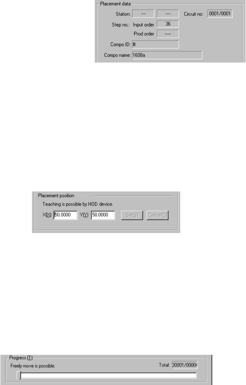
2) Placement data
① Station (available to a KE-2030 only)
The station whose component placement point is being tracked is
displayed here.
② Step no.
The step number of
Placement data
being tracked is
displayed here.
③ Compo ID
(Component ID)
The ID of a component being tracked is displayed here.
④ Compo name (Component name)
The name of a component being tracked is displayed here.
⑤ Circuit no
The circuit number being tracked/total number of circuits are displayed
here.
3) Placement position
The coordinates of a component placement position being tracked is
displayed here. You can manually change the coordinates or use the
teaching function to change the coordinates displayed.
4) <Set> and <Cancel> buttons
These buttons are activated when you manually change the coordinates or
use the teaching function to change them. When you click the <Set> button,
the changed coordinates are saved into Placement data. If you do not want
to save the changed coordinates, click the <Cancel> button.
5) Progress
This slide bar moves one by one as the tracking position moves. While the
tracking operation pauses, you can move this slider bar to move the tracking
position to the previous point, the next point and so on.