KE2010.Instruction Manual.Ver.2.01,Rev.08.pdf - 第326页
4 – 219 (5) Monitor display During tr acking , the f ollowing info rmation on each component placement posit ion is displayed on the monitor . Display of the center and four corners of a component varies depending on the…
4 – 218
(4) Operation during tracking
While the system is tracking a component placement position, you can use the
following keys/switches to control the tracking operation.
Operation Keyboard Operation panel HOD
Start of tracking F1 Start button ENTER
Stop of tracking F2 Stop button PAUSE
Moving to the previous point F5 PREVIOUS
Moving to the next point F6 NEXT
Component Verify check F7
SOT Angle check F8
Changing data F9
End of tracking Pressing the ESC
key while the
machine is stopping
Pressing the Stop
button while the
machine is stopping.
Pressing the
CANCEL button
while the machine is
stopping.
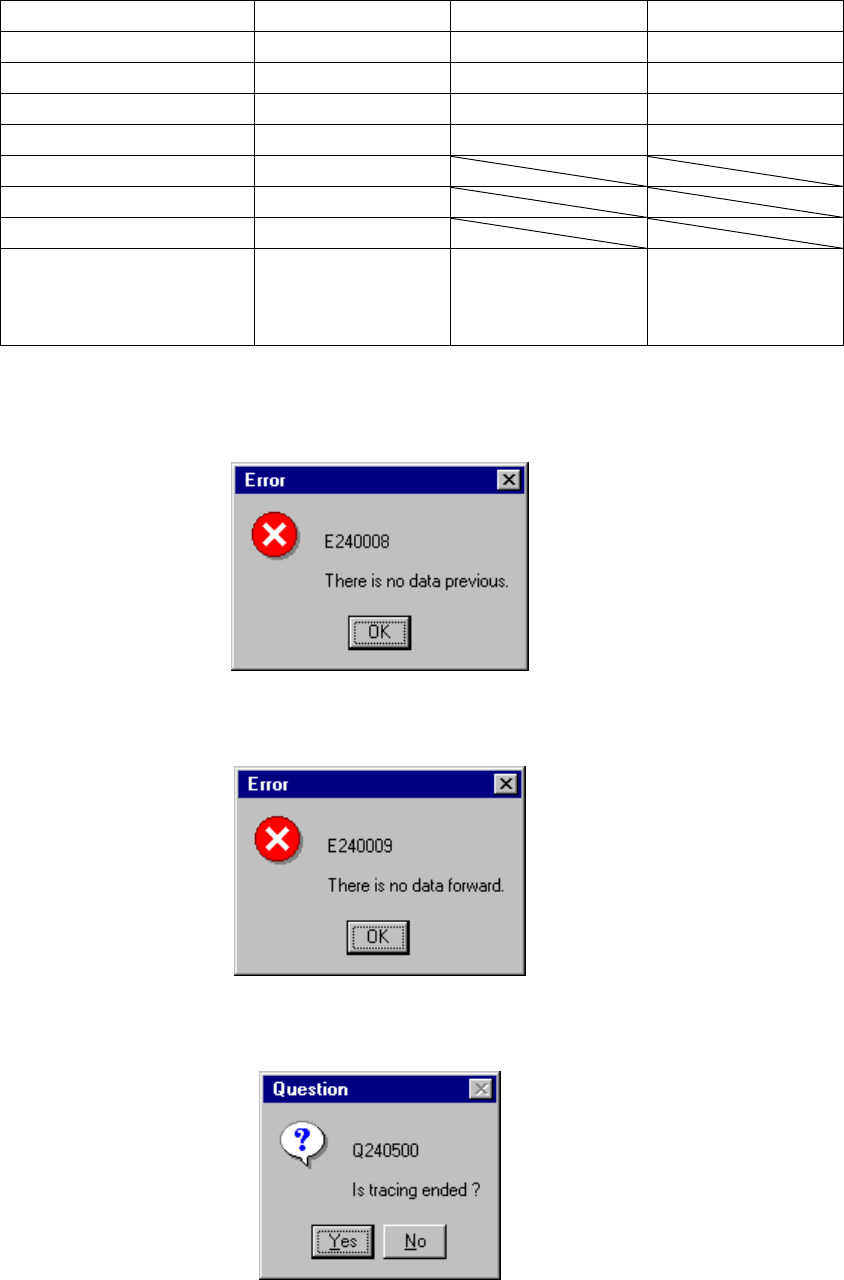
If there is no data when you try to move the camera to the previous point, the
following dialog box appears on the screen.
If there is no data when you try to move the camera to the next point, the following
dialog box appears on the screen.
If you abort the tracking operation due to either of the reasons above, the following
dialog box appears on the screen.
4 – 219
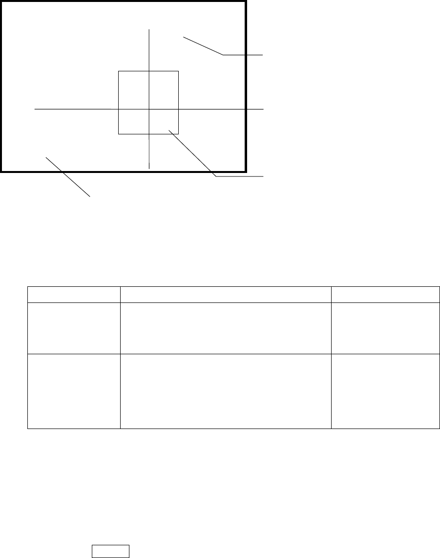
(5) Monitor display
During tracking, the following information on each component placement position
is displayed on the monitor.
Display of the center and four corners of a component varies depending on the
component size.
Component size Four corners of a component Center of a component
Component whose
shorter side is 4.5
mm or less
The window frame displayed on the monitor
indicates four corners of a component. A
placement point whose angle was set is displayed
by rotating the window frame itself.
Center of the point at
which lines are crossed.
Other components
(large components)
The camera moves to each set of coordinates of
four corners: [TOP-L], [TOP-R], [BTM-R] and
[BTM-L] in this order. For a component
placement point whose angle was set, the camera
moves to the coordinates obtained by rotating four
corners.
After the camera moves
to all of four corners,
[CENTER] is displayed
on the monitor. The
camera moves to the
center of a component.
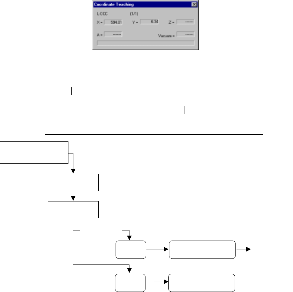
(6) Teaching coordinates during tracking
If the tracked coordinates are different from the actual ones, you can use the
HOD to teach the component placement point.
Step 1) Move the cursor to the X or Y coordinate.
Step 2) Press the HOD device button to teach the coordinates, then press the
ENTER key to validate them.
Indicates the coordinates viewed from the home position.
------- PLACE XY TRACE -------
Station:L R [ CENTER ]
Cur.No:
Pla.No :
Compo:
Angle :
Pos X : Y:
[CENTER]
indicates the center of a component.
[TOP-L] [TOP-R] [BTM-L] [BTM-R]
indicate four corners of a component
respectively: left on the top side, right on the
top side, left on the bottom side and right on
the bottom side.
Indicates the center or four corners of a component.
4 – 220
Figure 4.12.3.3.4 “Coordinate Teaching” dialog box
Step 3) To enable the validated coordinates, click the <Set> button or press the
ENTER key again.
To reset the validated coordinates to their original values, click the
<Cancel> button or press the CANCEL key.
Operation flow for teaching during tracking of a component placement point
4.12.3.4 Pick tracking/Height tracking
These commands allow the camera to track the component pick-up point. You can
see the component pick-up point displayed on the monitor, so you can use the HOD
to teach the pick-up point if the entered coordinates are not appropriate.
If you use the HMS, you can track the component pick-up height. In this case, the
system displays on the monitor values detected by the HMS one by one. If the
height of a component is quite different from that specified in Pick data, the system
teaches the height of a component in the same manner it does coordinates. (See
Chapter 6 “PRODUCTION PROCEDURES” for tracking during production.)
Move the input focus to the
component placement
coordinates XY edit box.
Press the HOD
device key.
Change
Placement data.
Teaching operation
ENTER
CANCEL
Click the <Set> button or
press the ENTER key.
Click the <Cancel> button
or press the CANCEL key.
After validating
the coordinates