KE2010.Instruction Manual.Ver.2.01,Rev.08.pdf - 第330页
4 – 223 2) Or der and range ① T he order of component data Enter t he range of Com ponent data used f or track ing: from the start point to the end point . As the def ault sett ing, all components are t o be track ed. ② …
4 – 222
To track the component pick-up height, select the [Height tracking] command on
the menu invoked from the "Machine Operation" menu provided with the Program
Editing utility. The following "Pick height tracking" dialog box appears on the
screen as shown in the figure below.
Figure 4.12.3.4.2 "Pick height tracking" dialog box
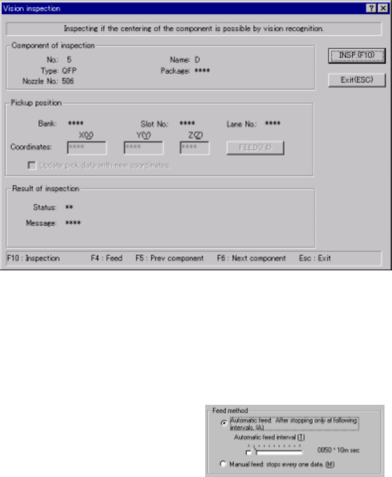
1) Feed method
① Automatic feed
The camera or HMS obtains a component pick-up point one by one at
regular intervals. The camera or HMS stops for the time of period
specified with the “Automatic
feed interval” slider bar
displayed below, then moves to
the next position.
(Automatic feed interval)
Use this slider bar to adjust the
stop time.
② Manual feed
The camera or HMS stops without moving to the next position until an
operator operates it.
4 – 223
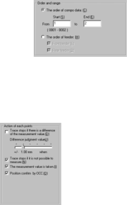
2) Order and range
① The order of component data
Enter the range of Component
data used for tracking: from the
start point to the end point. As
the default setting, all
components are to be tracked.
② The order of feeder
The camera or HMS tracks the front/rear of the feeder bank sequentially.
Select the feeder bank to be tracked.
3) Action of each points (displayed on the "Pick height tracking" dialog box)
The [Height tracking] command allows you to specify the action to be
performed after the machine moves to each tracking point.
① Trace stops if there is a difference of the measurement value.
If the difference between the value measured with the HMS and the
component pick-up height set in Pick data exceeds the "Difference
judgment level", the dialog box appears on the screen to stop the tracking
operation. (Difference judgment level)
Set the +/- upper and lower limits with the slider bar.
② Trace stops if it is not possible to measure.
If the HMS cannot measure the pick-up height (for example, because
there is no component at the measured pick-up point), the dialog box
appears on the screen to stop the tracking operation.
③ The measurement value is taken.
This choice allows you to save the value measured by the HMS into Pick
data by asking whether to save it for each point.
④ Position confirm by OCC.
Before moving the HMS to the pick-up point, you can check the pick-up
point on the VCS monitor.
After you specify the setting items, press the <Start> button or click the
<Execution> button.
When you click the <Exit> button, the system returns to the previous screen.
)
4 – 224
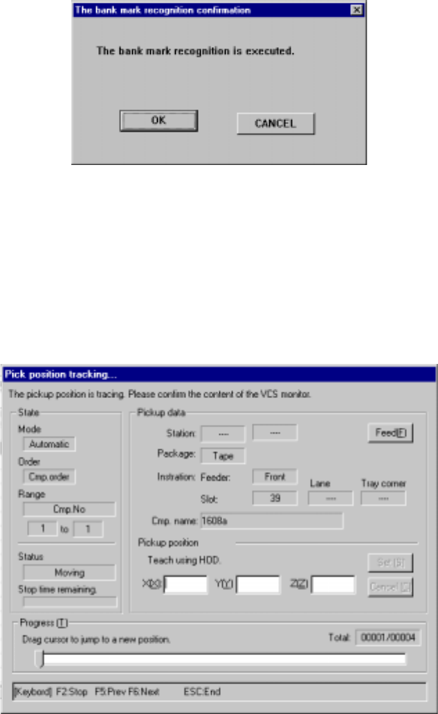
(2) Executing the bank mark alignment operation
If the bank mark recognition is set on the Setup menu, the system recognizes a
bank mark to improve the precision of the component pick-up point before the
camera or HMS moves to each feeder bank. The following dialog box appears
on the screen. Click the <OK> button. If you click the <Cancel> button, the
precision of the component pick-up point is not corrected.
Figure 4.12.3.4.3 “Feeder bank recognition confirmation” dialog box
(3) While the camera is tracking a component pick-up point/the HMS is tracking
component height
After you press the <Start> button or click the <Execution> button, the following
dialog box appears on the screen while the system is tracking each pick-up
position (height).
Figure 4.12.3.4.4 “Pickup position (height) camera trace” dialog box