KE2010.Instruction Manual.Ver.2.01,Rev.08.pdf - 第333页
4 – 226 3) Pickup position The coor dinates of a component pick -up position being track ed is displayed here. Y ou can manually change the coor dinates or use the t eaching funct ion to change the coor dinates displayed…
4 – 225
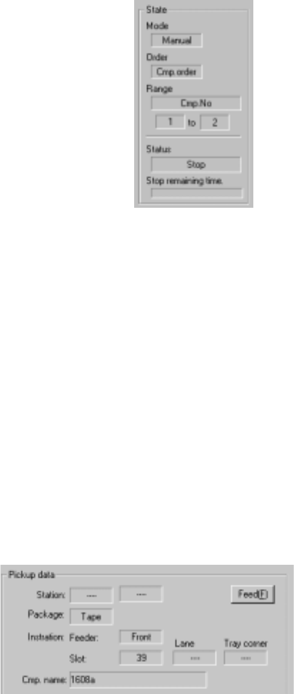
1) State
① Mode
“Manual” or “Automatic” which is set with the
radio button “Feed method” appears here.
② Order
“Feeder order” or “Cmp order” appears here as
specified with the “Order and Range” radio
button.
③ Range
The “first” component number and “end”
component number to be tracked are displayed
here. Or, which feeder bank is to be tracked is
displayed.
④ Status
“Operating” indicates that the axis is moving. “Pause” indicates that the
axis pauses temporally in Automatic Feed mode. “Stop” indicates that
the axis is stopped manually or intentionally. “Waiting” indicates that the
axis is moving to the safety position.
⑤ Stop remaining time
The progress bar indicates the remaining stop time in Automatic Feed
mode.
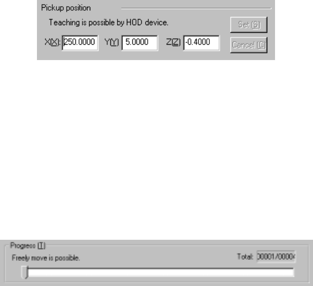
2) Pickup data
① Station (available to a KE-2030 only)
The station whose component pick-up point is being tracked is displayed
here.
② Package
The packaging style of a
component being tracked is
displayed here.
③ Installation Feeder
The fixing hole position of a
component being tracked is displayed here: if a stick feeder is used, the
lane number is displayed also, while if a tray is used, the corner number
is displayed also.
④ Cmp. name (Component name)
The name of a component being tracked is displayed here.
4 – 226
3) Pickup position
The coordinates of a component pick-up position being tracked is displayed
here. You can manually change the coordinates or use the teaching
function to change the coordinates displayed.
4) <Set> and <Cancel> buttons
These buttons are activated when you manually change the coordinates or
use the teaching function to change them. When you click the <Set> button,
the changed coordinates are saved into Pick data. If you do not want to
save the changed coordinates, click the <Cancel> button.
5) Progress
This slider bar moves one by one as the tracking position moves. While the
tracking operation pauses, you can move this slider bar to move the tracking
position to the previous point, the next point and so on.
4 – 227
(4) Operation during tracking
While the system is tracking a component pick-up position, you can use the
following keys/switches to control the tracking operation.
Operation Keyboard Operation panel HOD
Start of tracking F1 Start button ENTER
Stop of tracking F2 Stop button PAUSE
Moving to the previous point F5 PREVIOUS
Moving to the next point F6 NEXT
End of tracking Pressing the ESC
key while the
machine is stopping
Pressing the Stop
button while the
machine is stopping.
Pressing the PAUSE
button while the
machine is stopping.
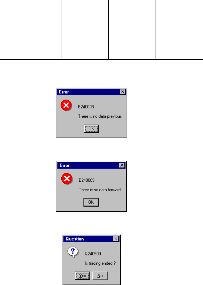
If there is no data when you try to move the camera or HMS to the previous point,
the following dialog box appears on the screen.
If there is no data when you try to move the camera or HMS to the next point, the
following dialog box appears on the screen.
If you finish the tracking operation due to either of the reasons above, the
following dialog box appears on the screen.