KE2010.Instruction Manual.Ver.2.01,Rev.08.pdf - 第336页
4 – 229 (Rear f eeder) Component size Four corners of a component Center of a component Component whose shorter side is 4.5 mm or less The w indow frame displayed on the monitor indicates four corners of a component. A p…
4 – 228
(5) Monitor display
①
During tracking, the following information on each component pick-up
position is displayed on the monitor.
Display of the center and four corners of a component varies depending on
the component size.
Four corners of a large component located on the front feeder may not be
displayed because the camera or HMS cannot always move to four corners.
(Front feeder)
Component size Four corners of a component Center of a component
Component whose
shorter side is 4.5
mm or less
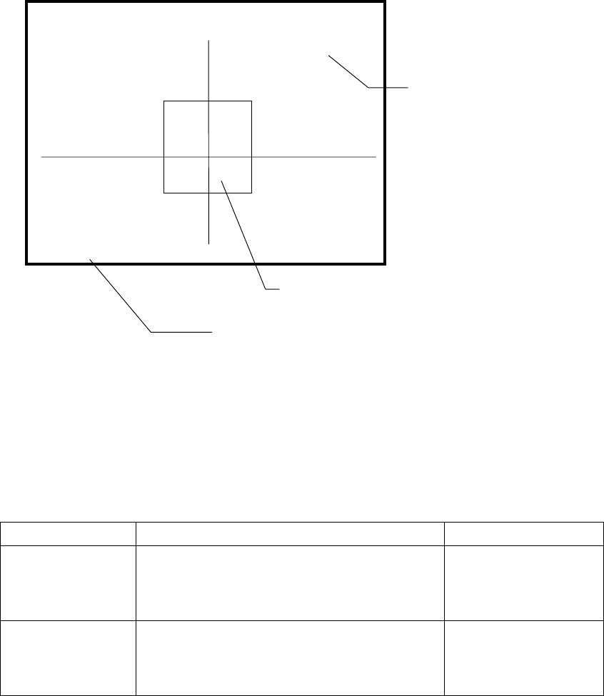
The window frame displayed on the monitor
indicates four corners of a component. A pick-up
point whose angle was set is displayed by rotating
the window frame itself.
Center of the point at
which lines are crossed.
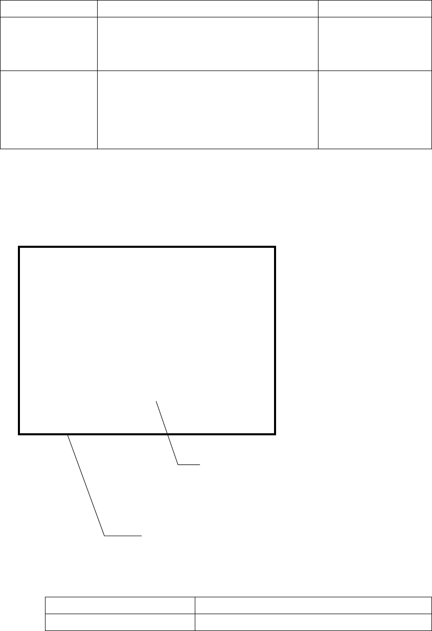
Other components
(large components)
[CENTER] is displayed
on the monitor, then the
camera moves to the
center of a component.
------- PICK XY TRACE -------
Station:L [CENTER]
Device:
Fdr No :
Compo:
Angle :
Pos X:
[CENTER]
indicates the center of a component.
[TOP-L] [TOP-R] [BTM-L] [BTM-R]
indicate four corners of a component
respectively: left on the top side,
right on the top side, left on the
bottom side and right on the bottom
side.
Indicates the coordinates viewed from the home position.
Indicates the center or four corners of a component.
4 – 229
(Rear feeder)
Component size Four corners of a component Center of a component
Component whose
shorter side is 4.5
mm or less
The window frame displayed on the monitor
indicates four corners of a component. A pick-up
point whose angle was set is displayed by rotating
the window frame itself.
Center of the point at
which lines are crossed.
Other components
(large components)
The camera moves to each set of coordinates of
four corners: [TOP-L], [TOP-R], [BTM-R] and
[BTM-L] in this order. For a component pick-up
point whose angle was set, the camera moves to
the coordinates obtained by rotating four corners.
After the camera moves
to all of four corners,
[CENTER] is displayed
on the monitor. The
camera moves to the
center of a component.
② Height tracking
While the HMS is tracking the component pick-up height, the following
information is displayed on the monitor.
The position measured with the HMS varies depending on the size of a
component as shown below.
Size of a component Component height measured position
All components Center of a component
------- PICK Z TRACE -------
Station:L
Device:
Fdr No :
Compo:
Angle :
Z :
Hms :
Pos
Indicates the coordinates viewed from the home position.
After the HMS stops at the center of a component, the
height specified in Pick data and that detected with the
HMS are displayed here.
If the HMS cannot detect the height, <*****> appears here.
4 – 230
(6) Teaching coordinates during tracking
If the tracked coordinates are different from the actual ones, you can use the
HOD to teach the component pick-up point.
Step 1) Move the cursor to the X, Y or Z coordinate.
Step 2) Press the HOD device button to teach the coordinates, then press the
ENTER key to validate them.
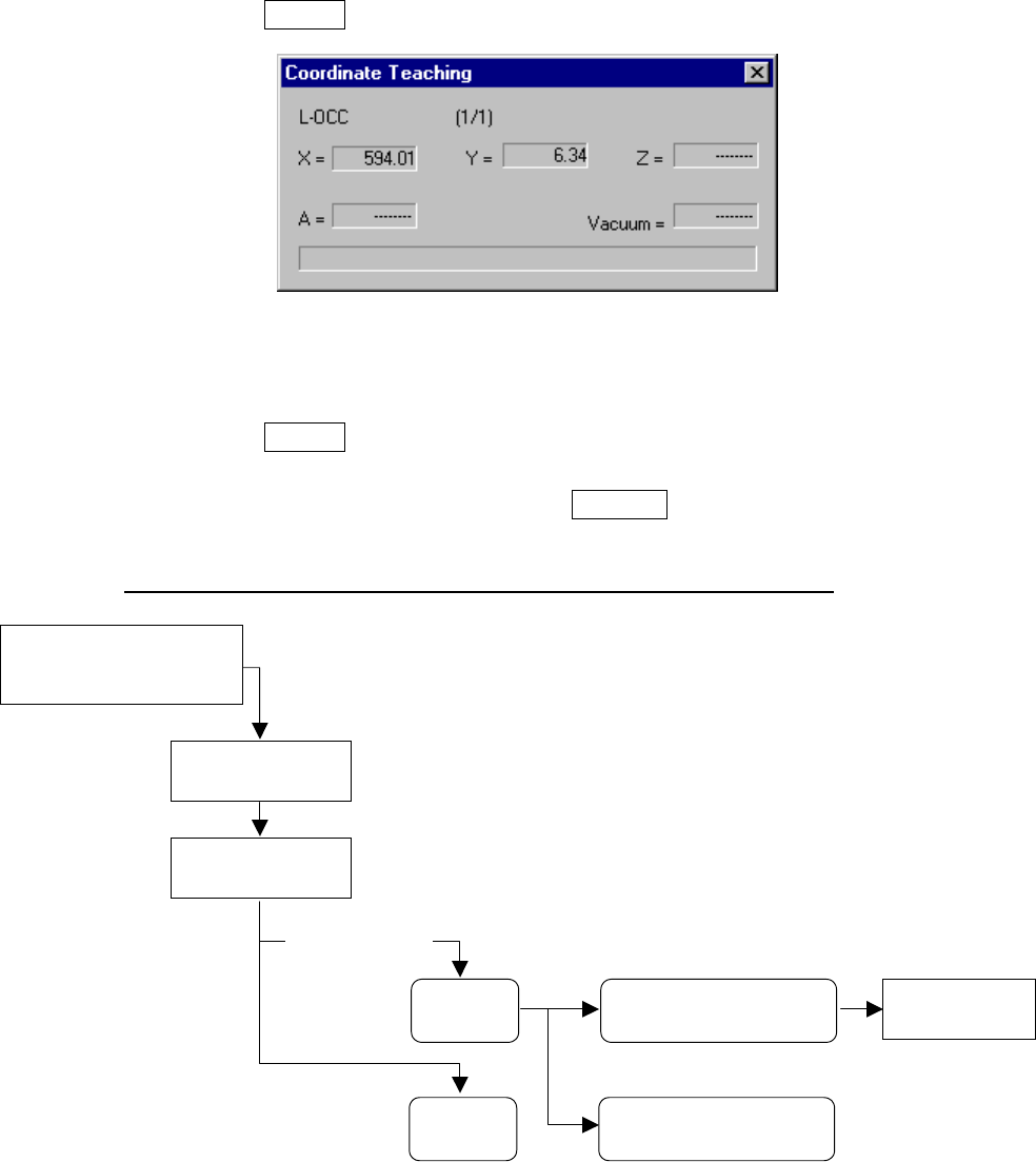
“Coordinate Teaching” dialog box
Step 3) To enable the validated coordinates, click the <Set> button or press the
ENTER key again.
To reset the validated coordinates to their original values, click the
<Cancel> button or press the CANCEL key.
Teaching operation flow during tracking of a component pick-up point
Move the input focus to the
component pick-up
coordinates XYZ edit box.
Press the HOD
device key.
Change Pick
data.
Teaching operation
ENTER
CANCEL
Click the <Set> button or
press the ENTER key.
Click the <Cancel> button
or press the CANCEL key.
After validating
t
h
e
coo
r
d
in
ates