KE2010.Instruction Manual.Ver.2.01,Rev.08.pdf - 第35页
1 − 18 (2) Area in w hich back up pins cannot be proved KE-2010M 20mm 21mm 22mm 0mm ~ 92mm 4mm 50mm 17.5mm 17.5mm Note: W hen the PW B is trans ferred from r ight to left, the marginal area of 50mm x 20mm is set on the l…
1 − 17
1.1.7 Printed circuit board specifications
1. Board size
Min. : X 50 mm x Y 30 mm
Note that the minimum size becomes 50 mm x 50 mm (X/Y) (optional)
when the machine is equipped with the automatic PWB width
adjustment function.
Max. : [KE-2010M] X 330 mm x Y 250 mm
[KE-2010L] X 410 mm x Y 360 mm
[KE-2010E] X 510 mm x Y 460 mm
X : Along the movement of the board
Y : From front to rear (and reversely) of the machine
2. Board thickness
Min. : 0.4 mm
Max. : 4 mm
3. Board warp limit
0.2 mm or less per 50 mm
1 mm or less both for upward and downward directions
(Conforms to JIS B 8641.)
4. Board limitations
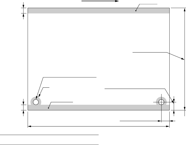
(1) Marginal area
3
3
Note: Dimension at the factory
Movement of PWB
Marginal area
Standard φ4
+0.1
mm
0
φ2.5 - φ4
+0.1
mm (Optional)
0
[KE-2010M] 30 - 250mm
[KE-2010L] 30 - 360mm
[KE-2010E] 30 - 460mm
5 ± 0.1mm
5 - 7mm for particular ordering (factory-set)
Marginal area
Conveying rail (fixed)
Standard 5 ± 0.1mm (Note)
[KE-2010M] 50 - 330mm, [KE-2010L] 50 - 410mm, [KE-2010E] 50 -510mm
1 − 18
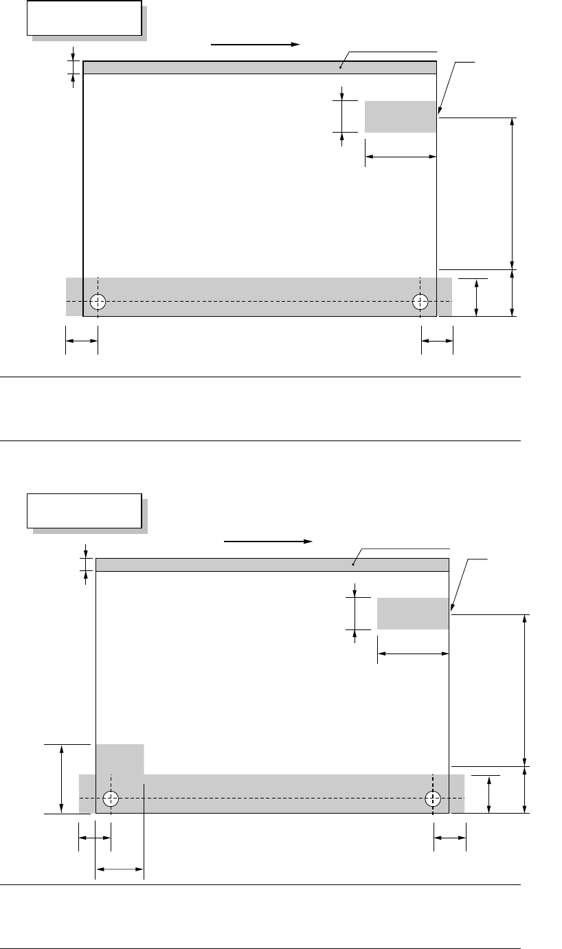
(2) Area in which backup pins cannot be proved KE-2010M
20mm
21mm
22mm
0mm ~ 92mm
4mm
50mm
17.5mm 17.5mm
Note: When the PWB is transferred from right to left, the marginal area of 50mm x
20mm is set on the left.
When the PWB is transferred from right to left, the marginal area of 36mm x
105mm is set on the right.
(3) Area in which backup pins cannot be proved KE-2010L
20mm
21mm
37mm
0mm ~ 178mm
4mm
50mm
17.5mm
36mm
17.5mm
105mm
Note: When the PWB is transferred from right to left, the marginal area of 50mm x
20mm is set on the left.
When the PWB is transferred from right to left, the marginal area of 36mm x
105mm is set on the right.105mm is set on the right.
Movement of PWB
Conveying rail (fixed)
Area in which backup
pins cannot be provided
(Variable)
(20 mm when the PWB is transferred from right to left)
Stopper position
Movement of PWB
Area in which backup
pins cannot be provided
Conveying rail (fixed)
(35 mm when the PWB is transferred from right to left)
Medium size board
s
p
ecifications
Large size board
s
p
ecifications
Stopper position
(Variable)
1 − 19
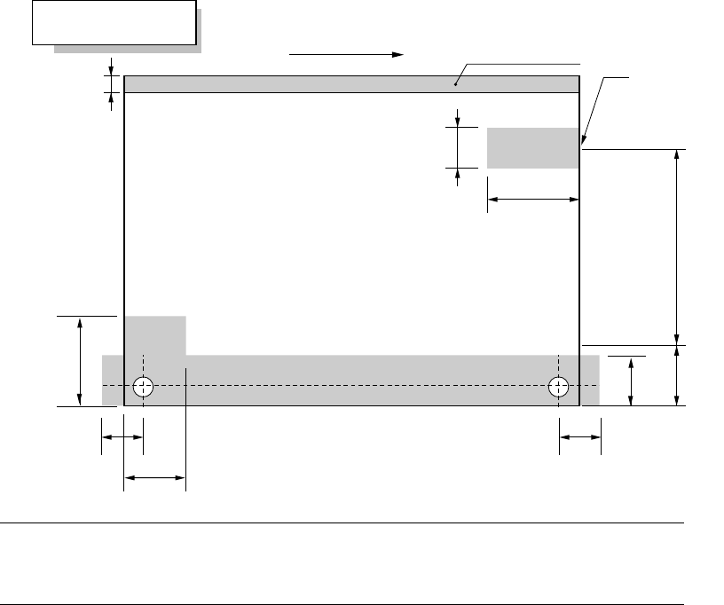
(4) Area in which backup pins cannot be proved KE-2010E
20mm
21mm
37mm
0mm ~220mm
4mm
50mm
17.5mm
36mm
17.5mm
105mm
Note: When the PWB is transferred from right to left, the marginal area of 50mm x
20mm is set on the left.
When the PWB is transferred from right to left, the marginal area of 36mm x
105mm is set on the right.
Movement of PWB
Conveying rail (fixed)
Area in which backup
pins cannot be provided
(Variable)
(35 mm when the PWB is transferred from right to left)
Stopper position
Extra large size
board s
p
ecifications