KE2010.Instruction Manual.Ver.2.01,Rev.08.pdf - 第355页
5 − 2 5.2 Functions (1) Coordinat es teaching The device names which can be taught and the teaching items ar e shown in T able 5.1 below . Note that the device names which are options not installed and t hose designated …
5 − 1
CHAPTER 5 TEACHING
This chapter describes how to perform teaching operation.
There are two types of teaching; one is for coordinates and the other for recognition.
This section starts describing teaching operation from how to operate the HOD which is
basically used for these two types of teaching operations.
5.1 How to Use the HOD
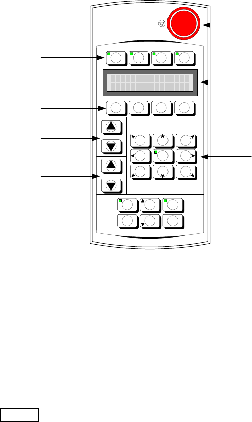
The appearance of the HOD is shown in Figure 5-1 below:
Figure 5-1 Appearance of the HOD
Use the DEV. NAME key to select a device other than the camera and HMS. To
select such a device, press either of two DEV. NAME keys (up or down direction) to
display the device name you want to select on the LCD.
Use the No. key to display (select) the device name and device number.
Use the ENTER key to validate your selection.
Use the move key to move the X- and Y-axes.
-X+Y +Z+Y +X+Y
-
θ
θθ
θ
-X +
θ
θθ
θ
+X
-X-Y -Z-Y +X-Y
FAST
DEV.NAME
No.
J U K I
F1 F2 F3 F4
NEXT
PREVIOUS PAUSEWINDOW
CANCEL ENTER
HMS CAMERA
VACUUM
ON/OFF
HEAD
Device selection keys
Function keys
No. keys
DEV. NAME
(
device name
)
ke
y
s
Move keys
Liquid crystal display
(
LCD
)
Emergency switch

5 − 2
5.2 Functions
(1) Coordinates teaching
The device names which can be taught and the teaching items are shown in Table
5.1 below. Note that the device names which are options not installed and those
designated as “Not to be used” on the Machine Setup menu cannot be selected.
Table 5.1 Teaching device and teaching items
Teaching coordinates (
○
): can be taught
Teaching device
X/Y
coordinates
Z coordinates
θ coordinates
Mark recognition
parameter
MNLA Head
○
○
FMLA Head
○
○
Bad mark sensor
○
OCC camera
○
○
OCC2 camera
○
○
HMS
○
○
The 1 POINT, 2 POINT, and 3 POINT device keys on the HOD become effective
when OCC camera is selected as the teaching devices. The 1 POINT key is the
default key when a device is selected.
When any other device key on the HOD is pressed while the machine is teaching
coordinates, the newly selected device moves to the coordinates defined by the
currently selected device, thus switching the device to be taught.
5 − 3
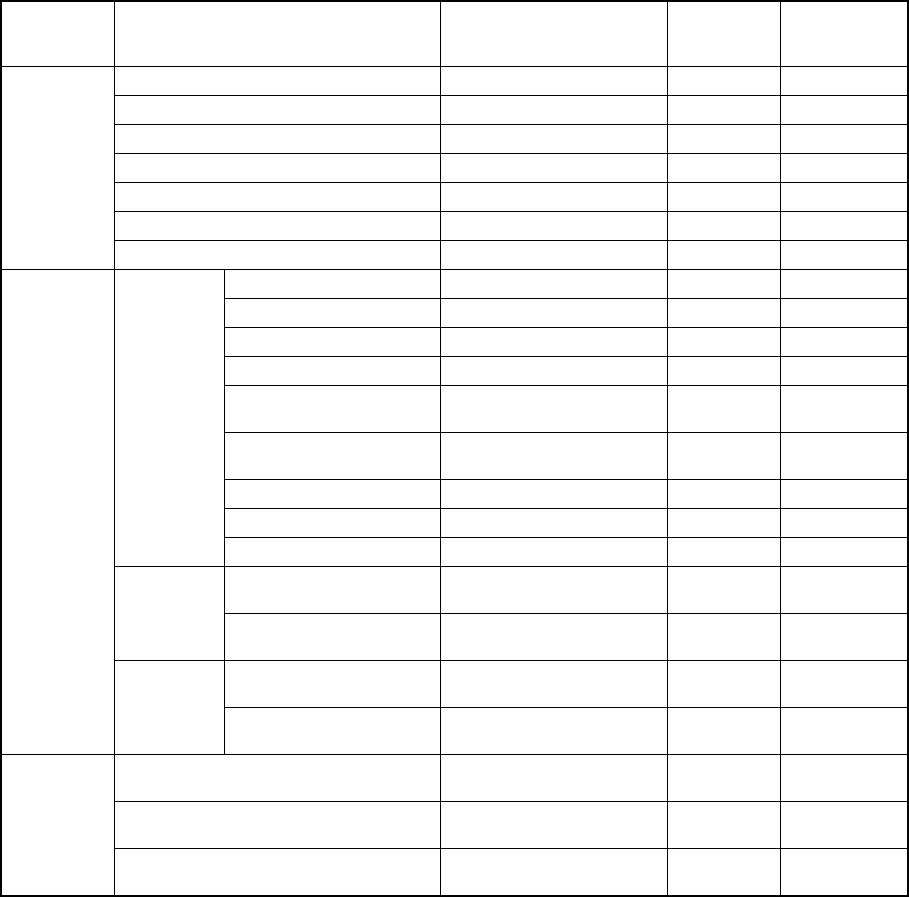
The detailed teaching items are shown in Table 5.2 below.
Table 5.2 Teaching items
Mode during
teaching
Input data item Data origin
Corrected by
Boc
alignment
Corrected by
Feeder bank
recognition
Reference pin position XY coordinates origin
Follower pin position XY coordinates origin
Shape clamp position XY coordinates origin
MTC shuttle pick position XY coordinates origin
Component discard position XY coordinates origin
Vacuum value without nozzle
Machine
setup
Head waiting position XY coordinates origin
Hole reference position Board reference position ○
PWB layout offset Board reference position ○
Circuit position reference Board reference position ○
Circuit position reference Board reference position ○
BOC mark position
Board reference position or
circuit reference position
*1 ○
BOC mark recognition
parameter
Bad mark position Circuit reference position ○
PWB height
PWB
PWB thickness
Placement position
Board reference position or
circuit reference position
*2 ○
Placement
data
IC mark position
Board reference position or
circuit reference position
*2 ○
Pick position XY
XY coordinates origin or rear
origin
*3 ○
Production
program
Pick data
Pick position Z
Z-axis origin (Top side of a
board)
Placement position XY
Board reference position or
circuit reference position
*2 ○
Pick position XY
XY coordinates origin or rear
origin
*3 ○
Production
Pick position Z
Z-axis origin (Top side of a
board)
* 1 For single pattern boards, the board reference position is used as the origin.
For matrix and non-matrix multiple pattern boards, when “PWB mark is used” is
selected as the BOC type board reference position is used as the origin, and when
“circuit mark is used” is selected as the BOC type the circuit reference position is
used as the origin.
* 2 For single pattern boards, the board reference position is used as the origin.
For matrix and non-matrix multiple pattern boards, the circuit reference position is
used as the origin.
* 3 For pick position of the component feeding devices installed on the front of the
machine, XY coordinates origin is used as the origin. For those installed on the
rear of the machine, the rear origin is used as the origin.