KE2010.Instruction Manual.Ver.2.01,Rev.08.pdf - 第363页
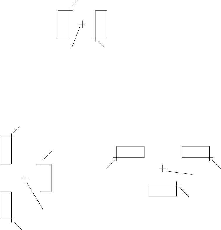
5 − 10 ① 2-point teaching A B C PWB pad Enter points A and B. The coordinat es of point C, which is the center bet ween points A and B, is then com puted and taug ht. ② 3-point teaching A B D C C A D B Enter points A, B,…
5 − 9
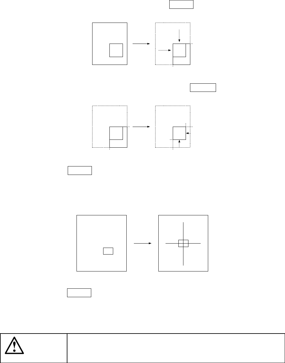
Move around the top, left, bottom, and right of the window frame using the axis
drive key for X- and Y-axes.
Move to the top and left first, and press the ENTER key.
Next, move to the bottom and right, and press the ENTER key.
When the ENTER key is pressed after moving to the bottom and right, the
camera moves so that the center of the window box is placed at the center of the
previous crosshair cursor. The window box is then changed to the crosshair
cursor.
Press the ENTER key here, to obtain the coordinates.
For 2- or 3-point teaching, perform as follows:
CAUTION
To avoid a risk of injury, do not place your hand in the machine, nor
move your face or head close to the machine while you are operating
the HOD.
5 − 10
①
2-point teaching
A
BC
PWB pad
Enter points A and B. The coordinates of point C, which is the center between
points A and B, is then computed and taught.
②
3-point teaching
A
B
D
C
C
A
D
B
Enter points A, B, and C. The coordinates of point D is then computed and
taught.
(Coordinate X of the point D is obtained as the center point between points A or B
and C; coordinate Y of the point D is obtained as the center point between points
A and B.)
Note that teaching of three points is effective only when the placement angle of a
component is 0, 90, 180, or 270 degrees.
D1
5 − 11
5.3.3 Teaching Z-axis
For Z-axis teaching, the operator must first select the device with which Z-axis is to be
taught as described in the procedure given in 5.3.1 “Basic operating procedure”.
Only the head and HMS can be selected as the device to teach the Z axis. An error
results with an alarm beep if any other device is selected, and the operator must start
the operation from the device selection.
This teaching is for height teaching. Move down slowly the nozzle tip until it touches
the object for measurement, and measure the height. Never push the nozzle into
the object.
To perform teaching with using the HMS, use the camera to teach the XY axes.
Move the camera to the measurement point, then press the HMS key of the device.
The HMS starts teaching operation and data entry is allowed with your pressing the
ENTER key.
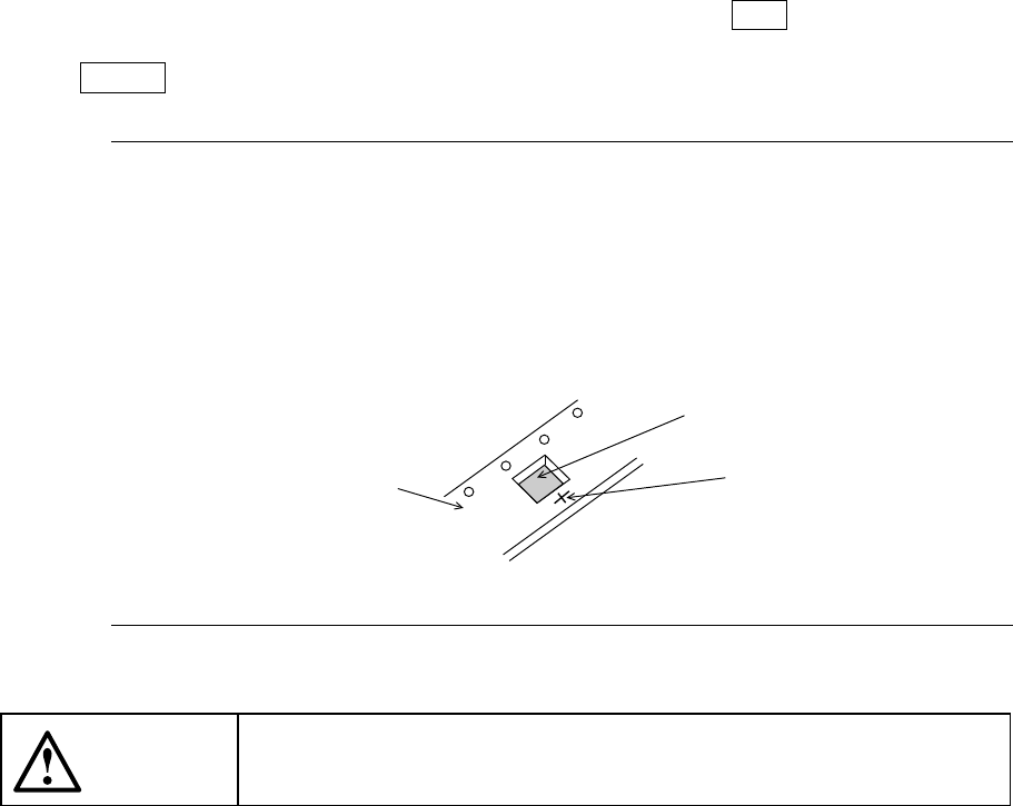
Note: When you use the HMS to perform teaching, laser beam is reflected at
random depending on the top side (side to be measured) surface condition
of a component to be measured (such as gloss and roughness), then the
component may not be measured. In this case, move the laser beam over
the tape carrier as shown in the figure below, then teach the Z axis by using
that spot as a substitute of the measured point.
CAUTION
When you use the HMS, avoid the direct of indirect (reflected with a
mirror or the like) laser beam getting into your eyes.
Tape carrier
Component
Measured point