KE2010.Instruction Manual.Ver.2.01,Rev.08.pdf - 第373页
5 − 20 Nex t, select “PR ” as the mark jud ge setting. Mov e the * ma rk over the posit ion of PR with the up and down arrow keys of the HOD (up and down arrow keys f or moving the XY axes), t hen press the ENTER key . “…
5 − 19
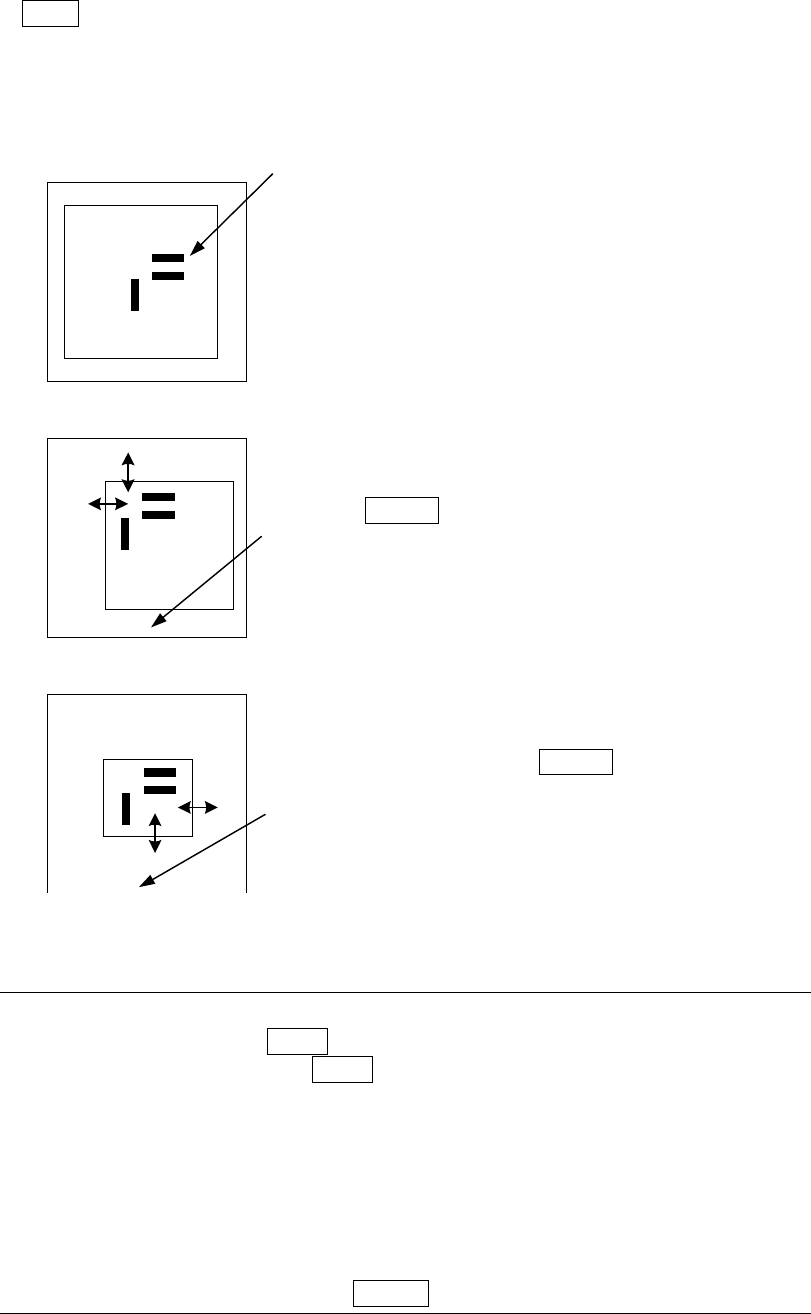
3. Teach the scale frame (template setting frame).
Use the up, down, left and right arrow keys to adjust and enter the scale frame
(FAST key changes the moving speed of the scale frame) in the order: upper
side, left side, bottom side, then right side.
The mark is automatically recognized, then the data necessary for correction is
obtained.
The image shot from the camera and the rectangle frames
are displayed.
Pad printing part
First, set the upper side and the left side of the scale
frame.
Set the upper side and left side to be recognized (by
moving the sides indicated with the arrow marks).
Press the ENTER key.
“Set Left-Top Point” appears at the bottom line of the
screen.
In the same manner, set the bottom side and the right side
of the scale frame.
After adjustments, press the ENTER key.
“Set Right-Bottom Point” appears at the bottom line of the
screen.
Note: To teach the scale frame only again without changing the information on
the mark, press the NEXT key of the HOD. Step 3 operation can be
skipped. However, the NEXT key pressing becomes invalid if the mark is
newly recognized.
The noise cut level around the mark is obtained, then displayed on the
monitor automatically.
Adjust the noise level so that the mark can be seen clearly and the noise
level can be decreased as much as possible with the up and down arrow
keys of the HOD (up/down arrow keys for moving X- and Y- axes).
After adjustments, press the ENTER key.
**********
**********
5 − 20
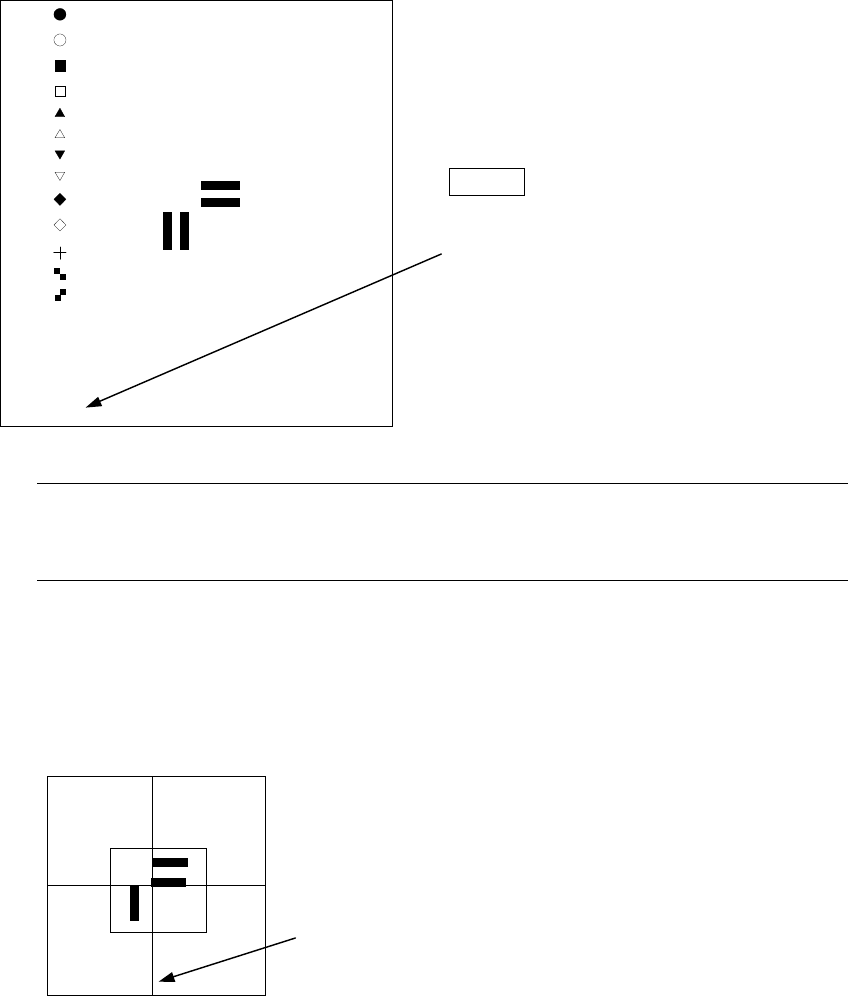
Next, select “PR” as the mark judge setting.
Move the * mark over the position of PR
with the up and down arrow keys of the
HOD (up and down arrow keys for
moving the XY axes), then press the
ENTER key.
“Select Mark by Up or Down Key”
appears on the bottom of the screen
.
Note: Since the template size does not exceed the size 256 x 256 pixels,
approximately quarter of the screen size selection of the template whose
size is too large displays an error, then the machine returns to Step 3.
④ Teach the center of the template screen.
The scale frame and the cross-hair cursor are
displayed on the screen.
Use the HOD to move the cross-hair cursor to decide
the center of the template (this position is matched with
the mark coordinates of the PWB data).
“TempMatch-Set Center” appears at the bottom of the
screen.
[ ]
[ ]
[ ]
[ ]
[ ]
[ ]
[ ]
[ ]
[ ]
[ ]
[ ]
[ ]
[ ]
[ *]PR
**********
**********
5 − 21
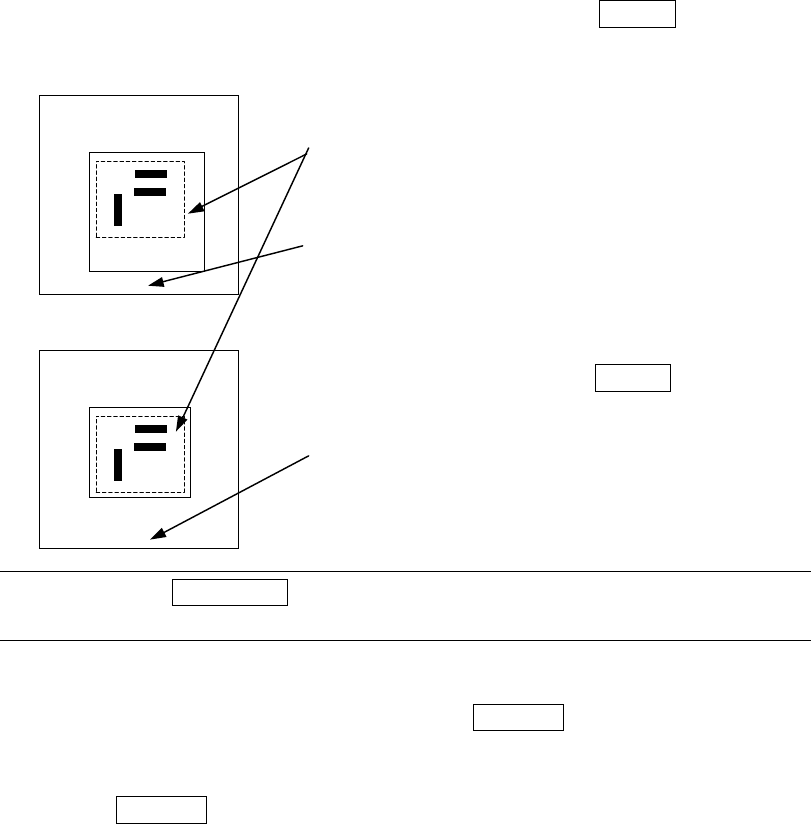
⑤ Teach the detection frame.
After Step 4 is performed, automatically the window whose size is 1.5 times of
that of the frame set in Step 3 appears at the position where the center of this
window is matched with the center of the screen itself (default window). To
change the size of the detection window, follow the instruction described under
Step 3.
If you do not have to change the detection frame, press the ENTER key only.
Set the detection frame in the same manner as the
scale frame.
The frame with the dotted line indicates the
template setting frame, and does not appear on
the screen actually.
“Set Left-Top Point” appears on the bottom of the
screen.
After adjustments, press the ENTER key.
“Set Right-Bottom Point” appears at the bottom of
the screen.
Note: When the PREVIOUS key of the HOD is pressed here, you can return to
the operation described under Step 3 (teaching of the scale frame).
⑥ After the mark recognition is taught completely, the T mark is displayed next to
the mark data, indicating that the mark is already taught. Perform the teaching
operation for all marks to be used. When the CANCEL key of the HOD is
pressed during teaching, the teaching operation is terminated in a half way.
(Data entered before you pressed this key becomes invalid).
When the CANCEL key is pressed, the device does not move.
Notes on setting the template
1) Check to see if there is no pattern similar with the template set inside the
detection frame.
2) Specify 0.5 to 3 mm as the pattern size in the same manner as the standard
mark.
3) Use the designed values (CAD data) as the coordinate value. With the user
defined template data, the center position of the pattern cannot be calculated
correctly. Since the mark is taught with moving the cross-hair cursor, the user
defined position becomes the center position (the normal mark generates no
error because the calculated center position becomes the center position of the
pattern).
4) The vision copy of the user defined template cannot be made.
**********
**********