KE2010.Instruction Manual.Ver.2.01,Rev.08.pdf - 第375页
5 − 22 5) T o stor e the production prog ram which uses the user def ined tem plate on the floppy disk, check to see if t here is enough space f or it . If ther e is not suff icient space on the disk, a production prog r…
5 − 21
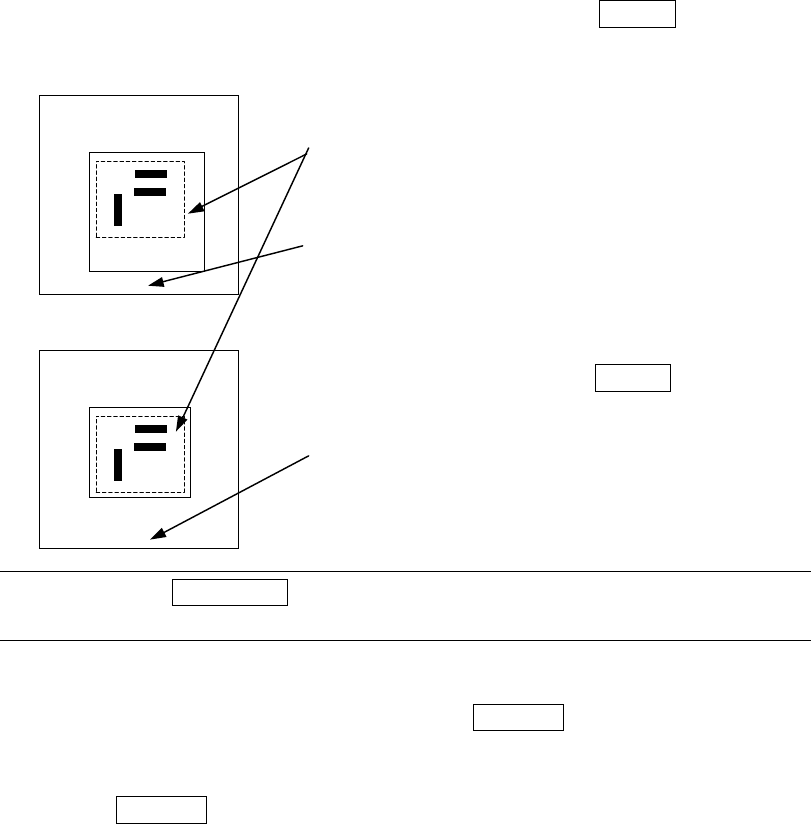
⑤ Teach the detection frame.
After Step 4 is performed, automatically the window whose size is 1.5 times of
that of the frame set in Step 3 appears at the position where the center of this
window is matched with the center of the screen itself (default window). To
change the size of the detection window, follow the instruction described under
Step 3.
If you do not have to change the detection frame, press the ENTER key only.
Set the detection frame in the same manner as the
scale frame.
The frame with the dotted line indicates the
template setting frame, and does not appear on
the screen actually.
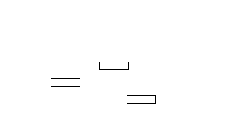
“Set Left-Top Point” appears on the bottom of the
screen.
After adjustments, press the ENTER key.
“Set Right-Bottom Point” appears at the bottom of
the screen.
Note: When the PREVIOUS key of the HOD is pressed here, you can return to
the operation described under Step 3 (teaching of the scale frame).
⑥ After the mark recognition is taught completely, the T mark is displayed next to
the mark data, indicating that the mark is already taught. Perform the teaching
operation for all marks to be used. When the CANCEL key of the HOD is
pressed during teaching, the teaching operation is terminated in a half way.
(Data entered before you pressed this key becomes invalid).
When the CANCEL key is pressed, the device does not move.
Notes on setting the template
1) Check to see if there is no pattern similar with the template set inside the
detection frame.
2) Specify 0.5 to 3 mm as the pattern size in the same manner as the standard
mark.
3) Use the designed values (CAD data) as the coordinate value. With the user
defined template data, the center position of the pattern cannot be calculated
correctly. Since the mark is taught with moving the cross-hair cursor, the user
defined position becomes the center position (the normal mark generates no
error because the calculated center position becomes the center position of the
pattern).
4) The vision copy of the user defined template cannot be made.
**********
**********
5 − 22
5) To store the production program which uses the user defined template on the
floppy disk, check to see if there is enough space for it. If there is not sufficient
space on the disk, a production program may not be stored.
6) Since it takes a long time for the production program which uses the user defined
template to be read from or store on the floppy disk, it is recommended that the
production program is not read nor stored from/onto the floppy disk directly.
7) To copy the production program which is stored on the hard disk, select the [File
Management (Explorer)] command on the [File] menu invoked from the main
menu to copy it onto a floppy disk.
Patterns which can be registered as the user defined template
− Patterns which can be registered as the user defined template
① Wiring pattern
② Pad and land pattern where no screen is printed (no solder paste is put)
③ PWB marks other than JUKI standard marks (whole or part)
− Notes on registration as the user defined template
① Through hole and pier hole
Since the pattern generation process is different from the holing process, the
same positioning cannot be always achieved. (The hole position is
undefined for a pattern.)
To register the template based on the through hole or pier hole, include the
wiring pattern around the hole.
− Pattern which cannot be registered as the user defined template
① Silk (character) pattern
Since the pattern and pad generation process is totally different from the silk
printing process, the placement position cannot be determined based on the
silk print.
② Pad and land pattern printed on the silk screen
The solder paste on the screen is in the form of grains, so lighting cannot be
stable depending on the environment or condition. The template matching
is highly appropriate for change of lighting conditions, but not for the change
of polarity (positive and negative).
③ The similar pattern is located on the same recognition screen
④ The template whose difference between the brightness and the darkness is
little.
5 − 23
⑤ Pattern whose scale (size) and/or angle changes
Especially if a part of the pattern is specified as the user defined template,
change of the scale affects the recognition accuracy. Therefore, specify
the entire pattern as the user defined template if possible.
The farther the gravity center of the template (as described above) is from
the that of the template, the more the angle change affects the recognition
operation: the recognition position is shifted. Set the user defined
template so that the gravity center of the template matches with the center of
the template as correctly as possible.
Note: The machine detects a white part as a mark. Whether the mark is
recognized as white or black with respect to the board color depends on the
contrast between the mark and the board, and on the light level for the
camera’s field of view. Normally, the mark is recognized as white. If,
however, there are lands, patterns, or silk printings around the field of view
of camera, the mark may be recognized as black with respect to the board
color. In this case, normal correction is impossible. Reverse the black
and white by pressing the CAMERA key on the HOD so that the mark
appears as white. If a mark is recognized as black against the board,
press the CAMERA key to reverse the black and white so that the mark can
be recognized as white.
Reverse display of the mark by the CAMERA key is possible only when you
are entering the scale frame.