KE2010.Instruction Manual.Ver.2.01,Rev.08.pdf - 第383页
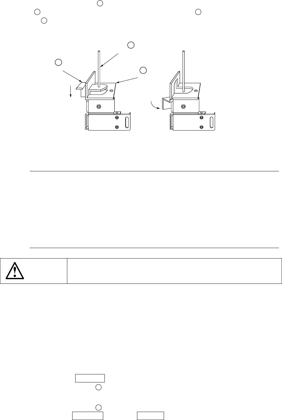
6 − 7 5) T he centering pin ⑭ 27 is not used. T heref ore, push down the stopper lever B and rotate it with hooking it over the dumper plate C so that the centering pin ⑭ 27 is pushed down to be locked. Figure 6.1.3. 6 N…
6 − 6
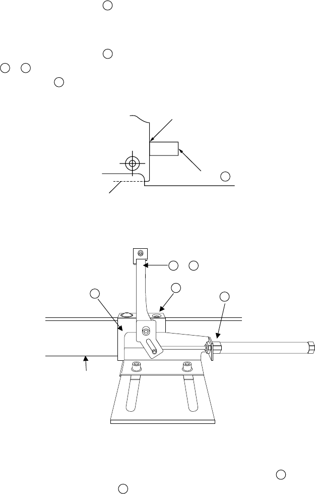
(4) Adjustment of the centering pin (Omitted for the use of pin reference)
(Figures 6.1.3.4, 6.1.3.5, 6.1.3.6)
1) Turn off the power, and also turn off the air valve.
2) Move the stopper
⑪
24
by hand, and push the production board (avoid the
center of the board and any cutouts of the board to contact the stopper)
against the stopper (as far as it goes).
3) Slide the guide block
36
in the X direction and manually fit the pusher A
44
,
45
with the edge of the board. There shall be no space between the
stopper
⑪
24
and the board.
Figure 6.1.3.4
Figure 6.1.3.5
4) While holding the guide block pushed to the supporting bar
38
, tighten the M4
hexagon socket head bolts
37
to lock the guide block.
Contact
⑪,
24
Board
44
,
45
37
38
36
Push in this direction.
6 − 7
5) The centering pin
⑭
27
is not used. Therefore, push down the stopper lever
B
and rotate it with hooking it over the dumper plate
C
so that the centering pin
⑭
27
is pushed down to be locked.
Figure 6.1.3.6
Notes:
Adjustment procedures 1) through 5) under (4) above can also be
adjusted manually by turning on the power and the air valve, and
using the independent control in the conveyor system of the manual
control and the automatic control.
When the stopper is moved, be sure to reenter the position of the
edge reference for the machine setup. If it is not reentered, the
reference position of the data is made differently.
There is no need of adjustment for the board of same specifications.
WARNING
Before starting to work, turn off the power of the machine to avoid a risk
of injury caused by unpredictable activation of the machine.
(5) Entering the position of the centering pin (Skip this step when the board outline is
used for reference) (Figure 6.1.3.6)
1) Turn on the power of the machine, and also turn on the air valve.
Perform zeroing (origin setting).
2) Lift up the BU plate ⑫ displaying the mechanical setup pop-up menu on the
"Machine setup" menu.
3) Select the [Reference pin position] on the [Setting Group] menu to select the
centering pin position.
4) Press the CAMERA key of the HOD. The OCC camera moves over the
centering pin ⑭
27
.
5) While observing the CRT screen, perform teaching for the center of the
centering pin ⑭
27
.
(Use the WINDOW key or the 2 POINT key.)
6) Next, perform teaching for the follower pin (see Section 7.2.2.3 of Chapter 7
"MACHINE SETUP").
⑭
27
C
B
6 − 8
WARNING
To avoid a risk of injury, do not place your hand in the machine, nor
move your face or head close to the machine during operation of the
HOD.
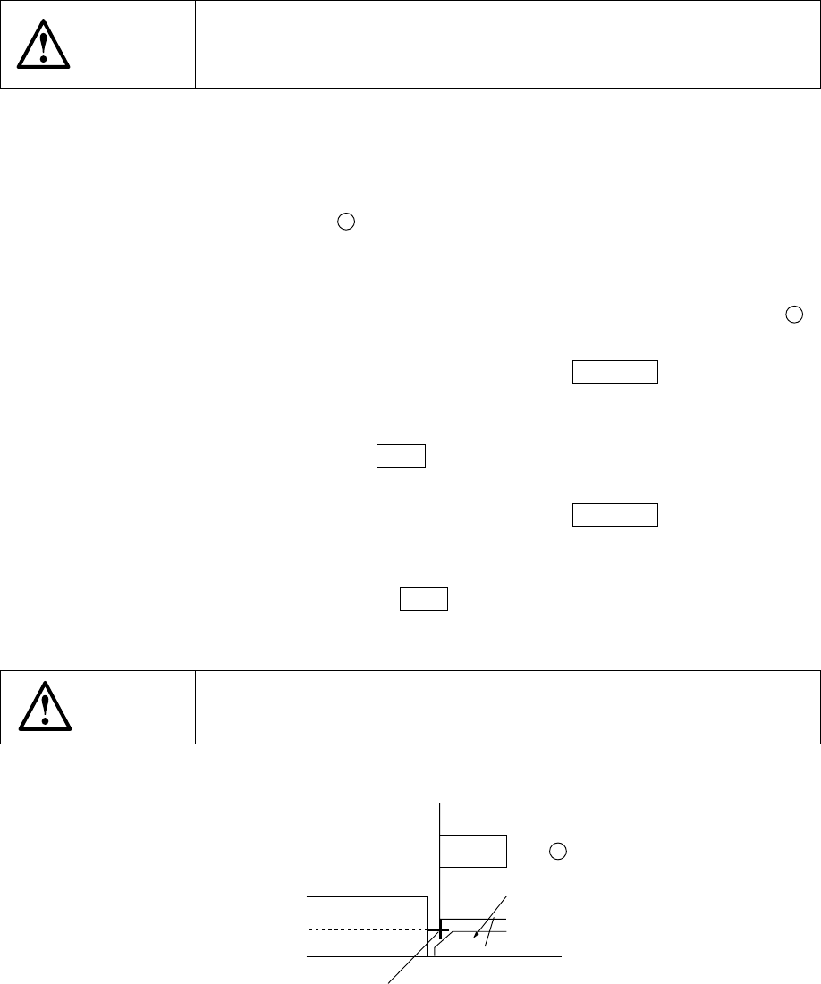
(6) Entering positions for the use of Board outline reference (Skip this step for the use
of pin reference) (Figure 6.1.3.7)
1) Turn off the machine, and also turn off the air valve.
2) Turn on the stopper ⑪
24
with displaying the mechanical setup pop-up menu
on the "Machine setup" menu.
3) Select [Shape clamp position] on the [Setting Group] menu.
4) Set a board on the board transfer rails, then push it against the stopper ⑪
24
lightly.
5) Align the cursor with the X window, then press the CAMERA key of the HOD.
The OCC camera moves to the current outline reference position.
6) While observing the CRT screen, align the crosshair cursor with the side of
the board. Then press the Enter key. Only the value of the X coordinate is
input. Note that a board should contact with the PWB guide closely.
7) Align the cursor with the Y window, then press the CAMERA key of the HOD.
The OCC camera returns to the outline reference position.
8) While observing the CRT screen, align the crosshair cursor with the side of
the PWB guide then press the Enter key. Only the value of the Y coordinate
is input.
WARNING
To avoid a risk of injury, do not place your hand in the machine, nor
move your face or head close to the machine.
Figure 6.1.3.7
Board
⑪
24
Stopper
Edge reference position
PWB guide