KE2010.Instruction Manual.Ver.2.01,Rev.08.pdf - 第386页
6 − 10 Figure 6.1.3. 9 4) The ST OP sensor ⑥ ⑲ and the C-OUT sensor ⑦ ⑳ are f ixed wi th t he stopper assembly, and they move tog ether with the stopper . 5) W hen the stopper assembly 39 has been moved, re-ent er the po…
6 − 9
6.1.3.3 Adjustments of Other Parts
(1) Odd shape board
The board sensor may missdetect the board if the board is an odd shape board
such as the board with cutouts. Therefore, enter the PWB transport sensor
delay time according to the size of the cutouts.
For the odd shape board, the positions of the stopper and board sensor can be
changed.
a. PWB transport sensor delay
1) Select "PWB conveyor" from "Set up group" of the machine setup.
(See Chapter 7 " MACHINE SETUP ".)
2) According to the length of the cutouts, enter the appropriate delay from
the keyboard. As a standard setting, set 60 ms for a cutouts of 30 mm
long.
Figure 6.1.3.8
3) If each PWB sensor does not detect the cutouts part of the board, delay
input is not necessary.
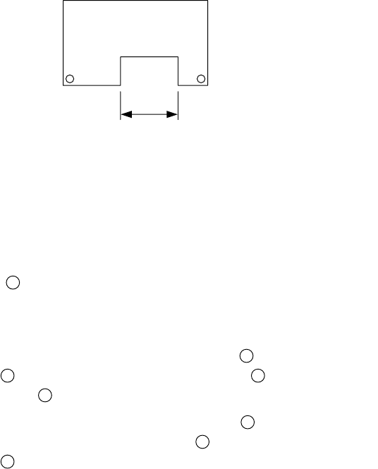
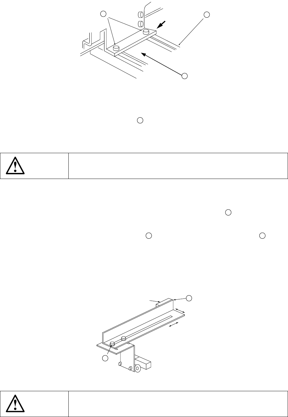
b. Stopper (Figure 6.1.3.1, Figure 6.1.3.9)
The stopper ⑪
24
can be moved in Y (plus, back) direction.
Move the stopper for the board which has a cutouts at its front edge.
1) Turn off the power of the machine, and also turn off the air valve.
2) Loosen the M4 hexagonal socket head bolts
40
used to fix the stopper
assembly
39
, and move the stopper assembly
39
along the long hole of
the rail support
41
.
3) Tighten the M4 hexagonal socket head bolts
40
at an appropriate
position, and fix the stopper assembly
39
. In this case, fix the stopper
assembly
39
while lightly pushing it in the direction of the arrow.
A: Cutouts length
A
:
6 − 10
Figure 6.1.3.9
4) The STOP sensor ⑥ ⑲ and the C-OUT sensor ⑦ ⑳ are fixed with the
stopper assembly, and they move together with the stopper.
5) When the stopper assembly
39
has been moved, re-enter the position by
referring to "6.1.3.2- (6) Entering positions for the use of Board outline
reference".
WARNING
Before starting to work, turn off the power of the machine to avoid a risk
of injury caused by unpredictable activation of the machine.
c. Board sensor (Figure 6.1.3.10)
The sensing positions of the IN sensor ① and the OUT sensor ② can be
changed by changing the fixed position of the sensor bracket
42
.
1) Turn off the power of the machine.
2) Loosen also the M3 hexagonal bolt
43
used to fix the sensor bracket B
42
, and
move it backward and forward or to the left and right along the long hole.
3) After adjustment is complete, tighten the screws.
4) Check that setting to the board is performed in transportation system of manual
control or that of program edit.
Figure 6.1.3.10
WARNING
Before starting to work, turn off the power of the machine to avoid a risk
of injury caused by unpredictable activation of the machine.
39
41
40
Pushing
43
①
②
42
6 − 11
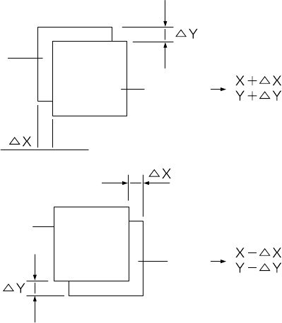
(2) Compensation
See Section 6.5 "Trial Run" to test-place components on one of the production
PWB and check for the deviations between elements and pads. When detecting
any deviation, compensate its X and Y coordinates in "Placement offset" in
Production mode.
Figure 6.1.3.11
(3) Notes on board transport
Note the following for board transport.
The three-motor conveyor uses the three buffers, so each operation (PWB
automatic transport, manual transport, and idle transport) is controlled according
these buffers.
Set PWBs above the IN sensor (Input buffer Entrance sensor), Stop sensor
(Centering buffer stop sensor) and OUT sensor (Output buffer Exit sensor)
respectively.
If a PWB is set between two sensors, various error occurs during board
transportation.
If a PWB is set above the C.OUT sensor, an error occurs also.
Pad
Pad
Element
Element