KE2010.Instruction Manual.Ver.2.01,Rev.08.pdf - 第388页
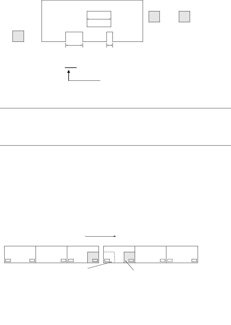
6 − 12 ① Transport sensor delay time (See Section 7. 2.2.8 "PW B conveyor" of Chapter 7 "MACHINE SETUP". ) IN STOP C.OUT W2 W1 W3 Cutouts leng th: W 2 > W 1 > W 3 Set to W 2 (Set to t he longest…
6 − 11
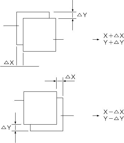
(2) Compensation
See Section 6.5 "Trial Run" to test-place components on one of the production
PWB and check for the deviations between elements and pads. When detecting
any deviation, compensate its X and Y coordinates in "Placement offset" in
Production mode.
Figure 6.1.3.11
(3) Notes on board transport
Note the following for board transport.
The three-motor conveyor uses the three buffers, so each operation (PWB
automatic transport, manual transport, and idle transport) is controlled according
these buffers.
Set PWBs above the IN sensor (Input buffer Entrance sensor), Stop sensor
(Centering buffer stop sensor) and OUT sensor (Output buffer Exit sensor)
respectively.
If a PWB is set between two sensors, various error occurs during board
transportation.
If a PWB is set above the C.OUT sensor, an error occurs also.
Pad
Pad
Element
Element
6 − 12
① Transport sensor delay time (See Section 7.2.2.8 "PWB conveyor" of Chapter
7 "MACHINE SETUP".)
IN
STOP C.OUT
W2
W1 W3
Cutouts length: W2 > W1 > W3
Set to W2 (Set to the longest one)
Example: Enter 10 mm or 20 mm.
Notes:
•
••
•
Do not set the delay of board transport sensor too long.
•
••
•
Especially be sure to set the value so that the sum of the PWB size (X
direction) and the delay setting should not exceed the maximum board
size (330 for the standard size, and 410 for the large size).
② When placing a board above the IN sensor, check that the red LED of the
sensor is lit.
③ When the machine stops operation because of an error of BOC mark
recognition, etc., recover it after stopping the machine on the previous stage
to enter it to the pause state.
④ <When the machine is connected to another machine>
NG
CENTER OUTIN
#1
CENTER OUTIN
#2
⑤ To produce boards with the connected machines, do not place a board in the
CENTER buffer nor OUT buffer.
(If a board is placed, it is fed to the next machine as the produced board.)
Transfer direction
If a board is located above the
OUT sensor of the machine #1
to be sent to the machine #2,
do not set a board above the IN
sensor of the machine #2
before production starts.
If a board is set above the
WAIT sensor, the board, which
is on the previous stage of the
machine #1, is set above the IN
buffer sensor after the board is
set above the Centering buffer
from the WAIT sensor.
6 − 13
⑥ If you press the Stop switch while the centering buffer is transferring a board, the
boards located in each buffer stop at the current position. (The dialog box
appears which asks whether to stop the board transfer operation.)
Select the "OK" button to stop the board transfer operation. (The CANCEL
button continues the transfer operation.)
On board transport specifications of a KE-2010L and KE-2010E
1. Board transport in Production mode
1) For a board whose width (X direction) is 50 mm to 330 mm, the system
functions in the same manner as the standard specifications of machine
does.
2) For a board whose width (X direction) is 331 mm or wider, the speed of the
center motor automatically decelerates to 300 mm/s, and the timing for
transferring a board onto the center buffer is: a board on the center buffer
is supplied when the stop sensor is turned off.
2. Board transport in Manual mode or Edit mode
See 2) above.