KE2010.Instruction Manual.Ver.2.01,Rev.08.pdf - 第389页
6 − 13 ⑥ If you press the Stop switch while the centering buf fer is transf err ing a board, the boards located in each buf f er stop at t he current position. (T he dialog box appears which asks whether to stop t he boa…
6 − 12
① Transport sensor delay time (See Section 7.2.2.8 "PWB conveyor" of Chapter
7 "MACHINE SETUP".)
IN
STOP C.OUT
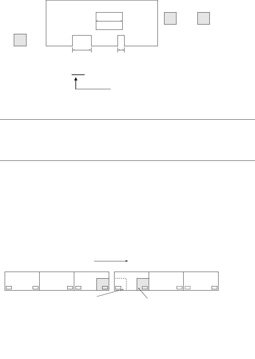
W2
W1 W3
Cutouts length: W2 > W1 > W3
Set to W2 (Set to the longest one)
Example: Enter 10 mm or 20 mm.
Notes:
•
••
•
Do not set the delay of board transport sensor too long.
•
••
•
Especially be sure to set the value so that the sum of the PWB size (X
direction) and the delay setting should not exceed the maximum board
size (330 for the standard size, and 410 for the large size).
② When placing a board above the IN sensor, check that the red LED of the
sensor is lit.
③ When the machine stops operation because of an error of BOC mark
recognition, etc., recover it after stopping the machine on the previous stage
to enter it to the pause state.
④ <When the machine is connected to another machine>
NG
CENTER OUTIN
#1
CENTER OUTIN
#2
⑤ To produce boards with the connected machines, do not place a board in the
CENTER buffer nor OUT buffer.
(If a board is placed, it is fed to the next machine as the produced board.)
Transfer direction
If a board is located above the
OUT sensor of the machine #1
to be sent to the machine #2,
do not set a board above the IN
sensor of the machine #2
before production starts.
If a board is set above the
WAIT sensor, the board, which
is on the previous stage of the
machine #1, is set above the IN
buffer sensor after the board is
set above the Centering buffer
from the WAIT sensor.
6 − 13
⑥ If you press the Stop switch while the centering buffer is transferring a board, the
boards located in each buffer stop at the current position. (The dialog box
appears which asks whether to stop the board transfer operation.)
Select the "OK" button to stop the board transfer operation. (The CANCEL
button continues the transfer operation.)
On board transport specifications of a KE-2010L and KE-2010E
1. Board transport in Production mode
1) For a board whose width (X direction) is 50 mm to 330 mm, the system
functions in the same manner as the standard specifications of machine
does.
2) For a board whose width (X direction) is 331 mm or wider, the speed of the
center motor automatically decelerates to 300 mm/s, and the timing for
transferring a board onto the center buffer is: a board on the center buffer
is supplied when the stop sensor is turned off.
2. Board transport in Manual mode or Edit mode
See 2) above.

6 − 14
6.2 Production
While the <ONLINE> indicator on the operator panel is off, the machine is in the
offline status and works as a standalone machine completely.
Contrarily when the <ONLINE> switch is pressed and the <ONLINE> indicator lights,
the machine is connected online to the HLC and functions under control of the HLC.
In Online mode, the producing conditions of the machine are all determined by the
HLC. (See the operation manual for details of the HLC.)
This section explains production in the Offline mode.
(1) Production main menu
Main menu Pull-down menu Sub menu Description
1 File See Section 4.2 "File". See Section 10.6 “Saving the
Machine Information” for how to save the machine
information.
2 View See Section 4.11 "Display".
1 PWB
Production
Displays the PWB production conditions dialog box
which allows you to set the conditions for PWB
production.
2 Trial Run Displays the Trial Run conditions dialog box which
allows you to set the conditions for trial run operation.
3 Production
conditions
3 Dry Run Displays the Dry Run conditions dialog box which
allows you to set the conditions for dry run operation.
1 Production
Condition
Screen
Displays the PWB Production screen which indicates
the settings done on the PWB Production conditions
dialog box or Operation option dialog box.
2 Production
status
Displays the screen which appears at start of
production and indicates data such as step No. used
during production.
1 Total Displays accumulated data unique to a production
program.
2 Left Front Displays accumulated data such as number of pick-up
operations already done per a pick-up position on the
left front side.
3 Left Rear Displays accumulated data per a pick-up position on
the left rear side.
4 Right Front Displays accumulated data per a pick-up position on
the right front side. (available with a KE-2030 only)
5 Right Rear Displays accumulated data per a pick-up position on
the right rear side. (available with a KE-2030 only)
6 Holder Displays accumulated data per a level of a tray holder.
7 MTC Displays accumulated data per a level of an MTC.
8 MTS Displays accumulated data per a level of an MTS.
9 Ratio of
Pick-up
Displays data in pick-up ratio order, that is, from the
highest ratio to the lowest ratio.
3 Management
Info.
10 Clear Clears all accumulated production management
information.
1 Vacuum level Displays the screen indicates data such as all place
rate used during production.
4 Window
4 Production info
2 I/O status Displays the I/O status during production.
1 Parts no. setup Displays the "Parts no. setup" dialog box which allows
you to set the number of components in Pick data.
2 Operation
option
Displays the Operation option dialog box which allows
you to make settings of operations to be done during
production.
1 Unplaced list Displays the Error Logging (Unplaced list) dialog box. 3 Retry list
2 Supplier
information
Displays the Error Logging (Supplier information) dialog
box.
1 Verify Current
check
Performs a single verify check.
2 Verify All check Performs a continuous verify check.
3 SOT Current
check
Performs a single SOT check.
4 SOT All check Performs a continuous SOT check.
4 Check
5 Laser check Checks the laser height.
5 Edit Data Changes Component data partially.
5 Tool
6 ATC control Displays the “AWC control” dialog box on the screen.