KE2010.Instruction Manual.Ver.2.01,Rev.08.pdf - 第390页
6 − 14 6.2 Production W hile the <ONLINE> indicator on the oper ator panel is of f , the m achine is in the off line stat us and works as a standalone machine com pletely. Contrarily when the <ONLINE> switch …
6 − 13
⑥ If you press the Stop switch while the centering buffer is transferring a board, the
boards located in each buffer stop at the current position. (The dialog box
appears which asks whether to stop the board transfer operation.)
Select the "OK" button to stop the board transfer operation. (The CANCEL
button continues the transfer operation.)
On board transport specifications of a KE-2010L and KE-2010E
1. Board transport in Production mode
1) For a board whose width (X direction) is 50 mm to 330 mm, the system
functions in the same manner as the standard specifications of machine
does.
2) For a board whose width (X direction) is 331 mm or wider, the speed of the
center motor automatically decelerates to 300 mm/s, and the timing for
transferring a board onto the center buffer is: a board on the center buffer
is supplied when the stop sensor is turned off.
2. Board transport in Manual mode or Edit mode
See 2) above.
6 − 14
6.2 Production
While the <ONLINE> indicator on the operator panel is off, the machine is in the
offline status and works as a standalone machine completely.
Contrarily when the <ONLINE> switch is pressed and the <ONLINE> indicator lights,
the machine is connected online to the HLC and functions under control of the HLC.
In Online mode, the producing conditions of the machine are all determined by the
HLC. (See the operation manual for details of the HLC.)
This section explains production in the Offline mode.
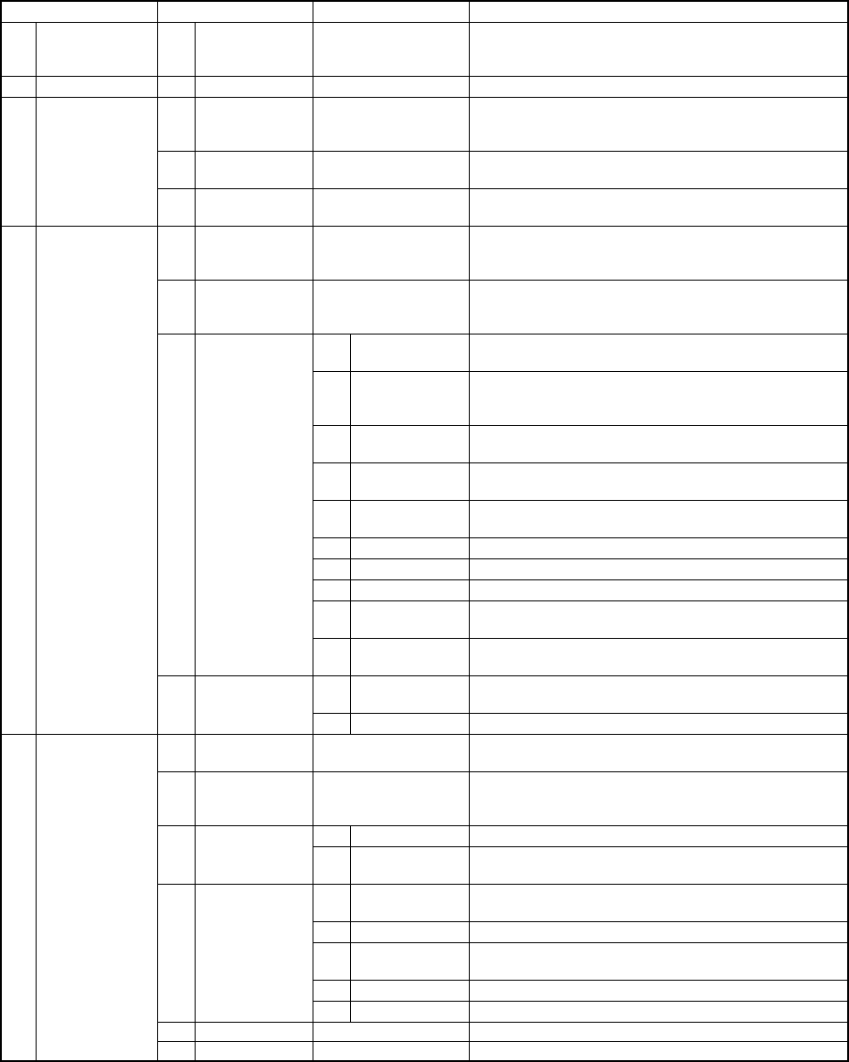
(1) Production main menu
Main menu Pull-down menu Sub menu Description
1 File See Section 4.2 "File". See Section 10.6 “Saving the
Machine Information” for how to save the machine
information.
2 View See Section 4.11 "Display".
1 PWB
Production
Displays the PWB production conditions dialog box
which allows you to set the conditions for PWB
production.
2 Trial Run Displays the Trial Run conditions dialog box which
allows you to set the conditions for trial run operation.
3 Production
conditions
3 Dry Run Displays the Dry Run conditions dialog box which
allows you to set the conditions for dry run operation.
1 Production
Condition
Screen
Displays the PWB Production screen which indicates
the settings done on the PWB Production conditions
dialog box or Operation option dialog box.
2 Production
status
Displays the screen which appears at start of
production and indicates data such as step No. used
during production.
1 Total Displays accumulated data unique to a production
program.
2 Left Front Displays accumulated data such as number of pick-up
operations already done per a pick-up position on the
left front side.
3 Left Rear Displays accumulated data per a pick-up position on
the left rear side.
4 Right Front Displays accumulated data per a pick-up position on
the right front side. (available with a KE-2030 only)
5 Right Rear Displays accumulated data per a pick-up position on
the right rear side. (available with a KE-2030 only)
6 Holder Displays accumulated data per a level of a tray holder.
7 MTC Displays accumulated data per a level of an MTC.
8 MTS Displays accumulated data per a level of an MTS.
9 Ratio of
Pick-up
Displays data in pick-up ratio order, that is, from the
highest ratio to the lowest ratio.
3 Management
Info.
10 Clear Clears all accumulated production management
information.
1 Vacuum level Displays the screen indicates data such as all place
rate used during production.
4 Window
4 Production info
2 I/O status Displays the I/O status during production.
1 Parts no. setup Displays the "Parts no. setup" dialog box which allows
you to set the number of components in Pick data.
2 Operation
option
Displays the Operation option dialog box which allows
you to make settings of operations to be done during
production.
1 Unplaced list Displays the Error Logging (Unplaced list) dialog box. 3 Retry list
2 Supplier
information
Displays the Error Logging (Supplier information) dialog
box.
1 Verify Current
check
Performs a single verify check.
2 Verify All check Performs a continuous verify check.
3 SOT Current
check
Performs a single SOT check.
4 SOT All check Performs a continuous SOT check.
4 Check
5 Laser check Checks the laser height.
5 Edit Data Changes Component data partially.
5 Tool
6 ATC control Displays the “AWC control” dialog box on the screen.
6 − 15
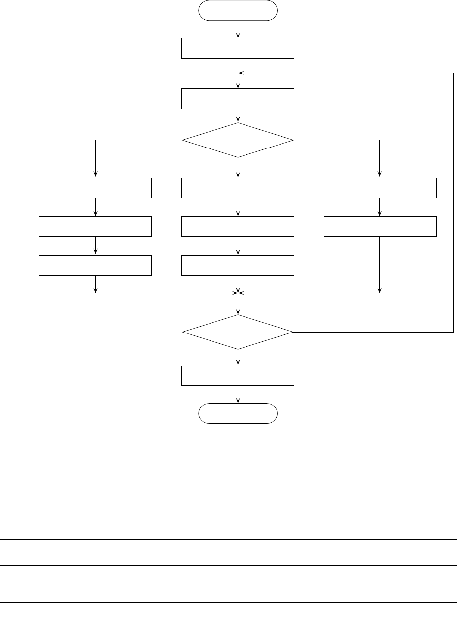
(2) Operation flow before the start of production
Select the producing conditions.
START
Specify the execution mode.
Execution mode?
Setting of
actual producing conditions
Setting of the number
of components to be placed
Board production
End?
N
Y
End
END
Setting of test-run conditions
Setting of the number
of components to be placed
Trial run
Setting of blank-run conditions
Blank run
Trial run Blank run
Board production
Figure 6.2.1 Production flow
(3) Production mode
There are three types of production modes.
No. Production mode Description
1 Board production mode Determines the number of PWBs on which components are placed, and
actually places components on the PWB.
2 Trial run mode Test-places a preset number of components on a PWB, check the status of
placement of components on the PWB. In case the placement is found not
satisfactory by the camera tracking function, teaching can be performed.
3 Blank run mode Test-runs the machine without using component. This mode is used to
check the pickup and placing operations of the machine.
Each of the above operations can have its operating conditions (production
condition, test-run condition, or blank-run condition).