KE2010.Instruction Manual.Ver.2.01,Rev.08.pdf - 第407页
6 − 31 No. Item Description 9 Momentary Stop time T he accumulated time of durations for which the machine cannot produce boards due to errors including a pause and emergency stop from start of production to end of produ…

6 − 30
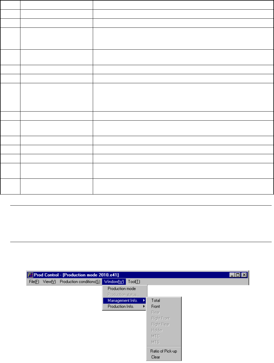
6.2.3 Production management information
In PWB production mode, production management information is stored. This
section explains the procedures for displaying the production management
information that has been stored.
(1) Conditions for creating the production management information data
①
When the production mode is set for the PWB production and the production
is performed for all placement positions.
②
Once the production data is created, new data for the next production is
added to the previous data.
If you want entirely new data to be created, clear the data already created.
(2) Items
①
Total management information
No. Item Description
1 Number of produced PWBs The number of boards produced after production management
information is cleared. (Only for complete boards)
2 Number of produced PWBs (Ckt) The number of produced circuits (Number of produced PWBs
×
Number of circuits - Number of bad marks detected)
3 Prod start time Date and time when the first production is started after the
production management information is cleared the last time.
4 Prod end time Date and time when the last production was ended with this
production program.
5 Operation time The time duration from when production was started to when the
production is completed excluding any stop time duration and the
conveyor waiting time. Pause time duration is also excluded.
6 PWB Carry in Waiting time The accumulated time of durations from when the clamped board is
released to when the IN sensor is set to ON.
Note that this indicates a value of the item “Carry out Waiting time”
if there is a board on the OUT buffer when the clamped board is
released. If there is no board on the OUT buffer and In sensor or
Wait sensor is already set to ON when the clamped board is
released, no time is added to this “PWB Carry in Waiting time”.
Even though the station pauses while it is waiting for a board to be
sent in, any pause time is not added to this “PWB Carry in Waiting
time”.
7 Carry out Waiting time The accumulated time of durations from when the clamped board is
released to when the OUT sensor is set to off (that is, when the
board located on the OUT buffer is ejected from the station) if the
OUT sensor is set to ON when the clamped board is released.
Note that any time is not added to this “Carry out Waiting time” if
there is no board on the OUT buffer when the clamped board is
released (For a KE-2030, the next process unit should be accept a
board from it.) However, in case of the last board, the time duration
from when the clamped board is released to when the station
finishes transporting it is added to this time of period regardless the
OUT sensor status: ON or OFF. Even though the station pauses
while it is waiting for a board to be ejected, any pause time is not
added to this “PWB Carry in Waiting time”.
8 Conveyor Waiting time The accumulated time of durations from when the system starts
transporting a PWB to when it finishes transporting the PWB. Even
though the station pauses while it is waiting for a board to be
transported, any pause time is not added to this “Conveyor Waiting
time”.
6 − 31
No. Item Description
9 Momentary Stop time The accumulated time of durations for which the machine cannot
produce boards due to errors including a pause and emergency stop
from start of production to end of production.
[Momentary Stop time] = [Stop time caused by trouble] + [Stop time
caused by Out-of-Component]
10 Maintenance stop time The accumulated time duration for which the machine pauses due to
a user request (by pressing the STOP key).
Pauses due to component protection or cycle stops are regarded as
a user request, and added to this “Maintenance stop time”.
11 Stop time caused by trouble The time duration obtained by adding system pauses: pauses as
the result you check the check box “Stop system on any error” on
the “Production (Pause) tab invoked from the Operation option
dialog box, pauses due to the condition the system cannot produce
any PWB (for example, the IC recovery belt is full of components),
and pauses due to asynchronous events (for example, the bank
moves down).
Note that if the system pauses because the stocked components run
out, the pause time duration is added to “Stop time caused by
Out-of-Component”
12 Stop time caused by
Out-of-Component
The accumulated time of durations for which the machine stops
because the stocked components run out or because it displays the
Retry list..
13 Stop time The total time duration of the "Maintenance stoop time", "Stop time
caused by trouble" and "Stop time caused by Out-of-Component".
14 Ratio of Pick-up (Number of normal pick-up operations / (Number of normal pick-up
operations + Number of pick-up errors)
×
100
15 Ratio of Placement (Number of normal placement operations / (Number of normal
pick-up operations + Number of pick-up errors)
×
100
16 Ratio of Retry 100 - "Ratio of Pick-up"
17 Number of Picked components This means the number of successfully picked components.
18 Number of Placed components This means the number of successfully placed components.
19 Number of Detect Bad mark This means the number of defective circuits detected.
20 Number of BOC mark This means the number of BOC mark recognition errors.
21 Number of IC mark This means the number of IC mark recognition errors.
22 Number of STOP caused by out of
component
This means the number of times the machine stopped because the
stocked components run out.
6 − 32
②
Management information per feeder
No. Item Description
1 Total Picked The number of pick-up operations from the feeder.
2 Picked The number of components successfully picked from the feeder.
3 Total Miss The number of components that are lost from the feeder.
(“Total Picked” – “Retry” × (“Retry” of Component data + 1) – “Placed”)
<For an MTC only, (Total Picked” – “Placed”)
4 Placed The number of components successfully picked , then placed from the
feeder.
5 Pick Err. The number of pickup errors occurred at the feeder.
6 Empty Comp. How many times the stocked components run out at the feeder.
7 Retry The number of retry over errors occurred at the feeder.
(The machine picks up a component the number of times set at the menu
item “Retry” on the Component data screen, and increases the counter by
“1” if it cannot pick up a component.)
8 LA Recog The number of laser recognition retry over errors occurred at the feeder.
9 Vrecog The number of VCS recognition errors which occurred at the feeder
(available with a KE-2020/2040 only.)
10 Lead The number of components whose bent lead(s) was (were) detected.
11 Dimension The number of components whose dimensions were incorrect.
12 Vrfy The number of components which causes a verify errors.
13 Chip The number of components that are picked from the feeder and cause a
chip rise error.
14 Cpla The number of components whose floating lead(s) was (were) detected
with the coplanarity check.
Note: For a component fed by a feeder, the retry error means that the stocked
components run out. For a component fed by a tray, when the number of
remaining components reaches zero, it is regarded as “Empty Comp.” error, and the
retry over error is detected according to the number of retries already performed.
6.2.3.1 Basic operation to display production management information