KE2010.Instruction Manual.Ver.2.01,Rev.08.pdf - 第416页
6 − 40 (3) Basic oper ation to display production inf orm ation W hen you select the [W indow] command on the menu bar, and then the [Production Inf o.] command and [ Vacuum level] command on the displayed menu in this o…
6 − 39
6.2.4
Production information
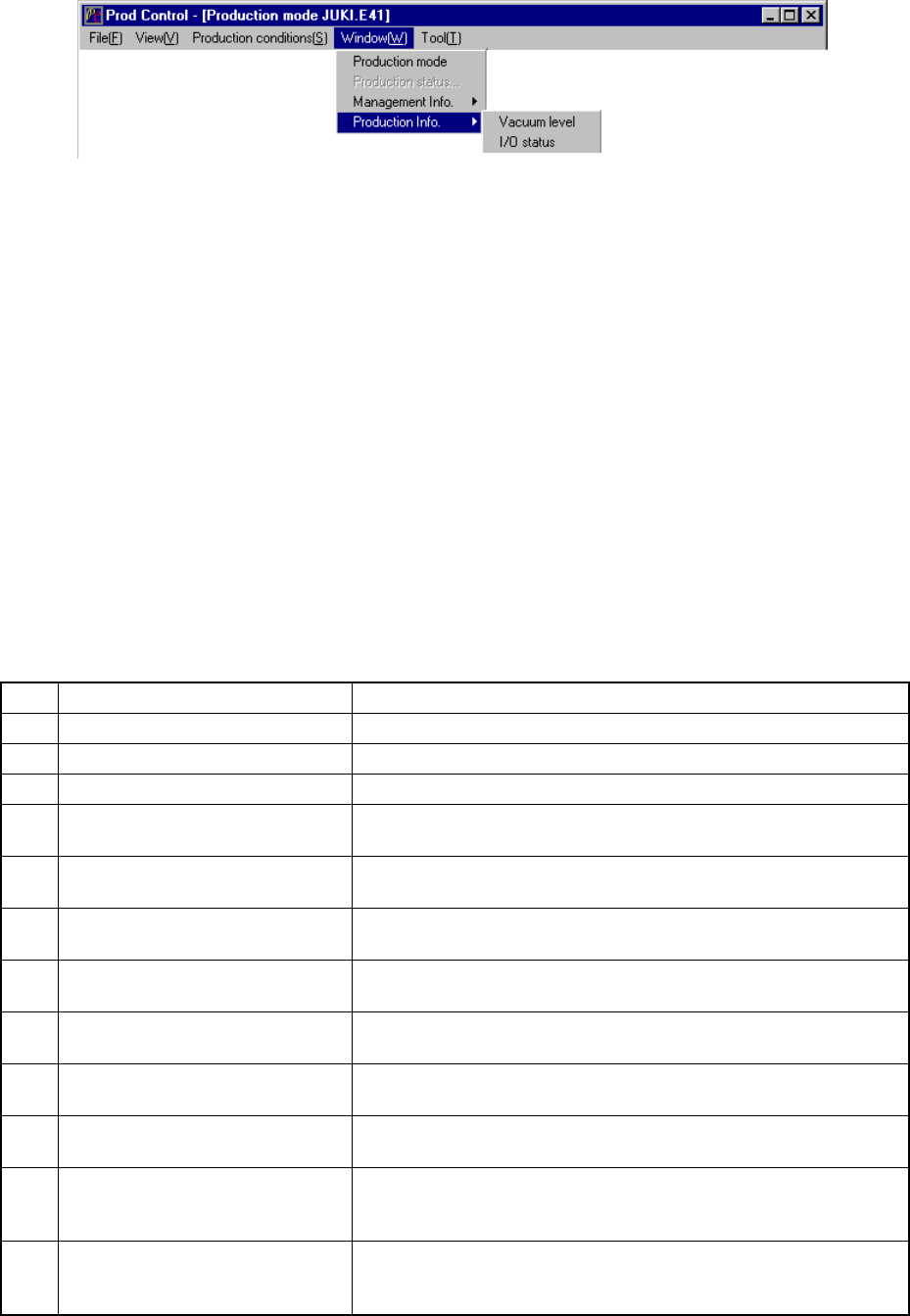
Figure 6.2.4.1 Selecting the [Production Info.] command
6.2.4.1 Vacuum level
When you select this command, the system displays information such as the cycle
time per board, total mounting ratio, total picking-up ratio, and vacuum value.
This command shows the vacuum level.
(1) Vacuum level display conditions
① When the production mode is set for the PWB production.
② Once all place rate and all pick rate is displayed, new data for the next
production is added to the previous data.
If you want entirely new data to be created, clear the data already created
from production management information.
(2) Items
① Total management information
No. Item Description
1 Tact on a board Procedure time on a board.
2 All Place Rate Shows the component placement ratio of the entire machine.
3 All Pick Rate Shows the component pick-up ratio of the entire machine.
4 Pick Pos. Shows that the machine is picking up a component or moving it to
the pick-up position.
5 After component picked Shows the current vacuum level obtained after the left and right
heads pick up components.
6 Before component placed Shows the current vacuum level obtained after the left and right
heads place components on a board.
7 Attaching a nozzle
(no component)
Shows the current vacuum level obtained when the left and right
heads use a nozzle before placing a component.
8 Picking a component
(component data)
Shows the current vacuum level obtained when the left and right
heads pick up components (according to Component data).
9 After component picked
thresholed
Shows the current threshold value obtained after the left and right
heads pick up components.
10 Before component placed
thresholed
Shows the current threshold value obtained before the left and right
heads place components on a board.
11 Judged result of vacuum error
(after comp. picked)
Shows the result obtained with comparing the current threshold
value obtained after the left and right heads pick up components
with the current vacuum level.
12 Judging result of vacuum error
(before comp. placed)
Shows the result obtained with comparing the current threshold
value obtained before the left and right heads place components on
a board with the current vacuum level.
6 − 40
(3) Basic operation to display production information
When you select the [Window] command on the menu bar, and then the
[Production Info.] command and [Vacuum level] command on the displayed
menu in this order, the system displays the following screen indicating the
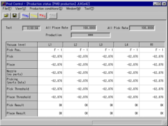
vacuum level (Figure 6.2.4.2).
Figure 6.2.4.2 Vacuum level
To clear all pick rate and all place rate of the production information displayed on the
screen,select the [Window] command from the menu bar,the [Managemen info.]
command on the dsiplayed menu,then the [Clear] command.
To clear tact,all pick rate and all place rate of the production information displayed on
the screen,when the file reading.
− The tact is showed producing and idling.
− Shown used to produced tact in idling.
− Shown vacuum level used during production.

6 − 41
6.2.4.2 I/O status
When you select this command, the system displays information such as PWB
transport, ATC and knock pin status to allow you to check each I/O condition.
(1) Menu items
① I/O status
No. Item Description
1 Stopper Displays the stopper ON/OFF status.
2 Side clamp X Displays the dimension reference cylinder X ON/OFF status.
3 Side clamp Y Displays the dimension reference cylinder Y ON/OFF status.
4 Ready in Displays the Ready In signal ON/OFF status.
5 Board available in Displays the Board Available In signal ON/OFF status.
6 IN sensor Displays the IN sensor ON/OFF status.
7 OUT sensor Displays the OUT sensor ON/OFF status.
8 WAIT sensor Displays the WAIT sensor ON/OFF status.
9 STOP sensor Displays the STOP sensor ON/OFF status.
10 C-OUT sensor Displays the C-OUT sensor ON/OFF status.
11 Conveyor in-motor Displays the PWB transport motor (IN buffer) ON/OFF status.
12 Conveyor center-motor Displays the PWB transport motor (center buffer) ON/OFF status.
13 Conveyor out-motor Displays the PWB transport motor (OUT buffer) ON/OFF status.
14 Reference pin sensor Displays the reference pin sensor ON/OFF status.
15 Support tbl. org. snsr. Displays the support table origin sensor ON/OFF status.
16 Support table position Displays the support table position.
17 Support tbl stp. snsr. Displays the support plate stopper ON/OFF status.
18 Entrance shutter Displays the open/close condition of the entrance shutter cylinder sensor.
19 Exit shutter Displays the open/close condition of the exit shutter cylinder sensor.
20 Through sensor Displays the open/close condition of the exit shutter board pass-through
sensor.
21 Air pressure drop
sensor
Displays the air pressure decrease sensor ON/OFF status.
22 Front feeder trolley pos.
snsr.
Displays the trolley position sensor (front side) ON/OFF status.
23 Rear feeder trolley pos.
snsr.
Displays the trolley position sensor (rear side) ON/OFF status.
24 Front feeder float
detector
Displays the feeder float sensor (front) ON/OFF status.
25 Rear feeder float
detector
Displays the feeder float sensor (rear) ON/OFF status.
26 Interference detector Displays the interference unit detection sensor ON/OFF status.
27 Cover open sensor Displays the cover open sensor ON/OFF status.
28 Thermometer Displays a value the thermometer indicates.
29 Vacuum calibration Displays a vacuum level value of the vacuum calibration.
The system displays the status of each sensor/unit when it controls the sensor/unit
completely.
The system always displays the status of each sensor, each signal and each unit.