KE2010.Instruction Manual.Ver.2.01,Rev.08.pdf - 第418页
6 − 42 (2) Basic Operations W hen you select the [W indow] command on the menu bar, and select the [Production Info.] command and the [I/O status] command on the displayed menu in this order, the sy stem displays the scr…

6 − 41
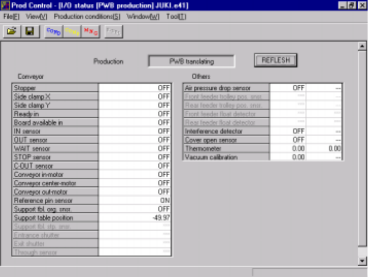
6.2.4.2 I/O status
When you select this command, the system displays information such as PWB
transport, ATC and knock pin status to allow you to check each I/O condition.
(1) Menu items
① I/O status
No. Item Description
1 Stopper Displays the stopper ON/OFF status.
2 Side clamp X Displays the dimension reference cylinder X ON/OFF status.
3 Side clamp Y Displays the dimension reference cylinder Y ON/OFF status.
4 Ready in Displays the Ready In signal ON/OFF status.
5 Board available in Displays the Board Available In signal ON/OFF status.
6 IN sensor Displays the IN sensor ON/OFF status.
7 OUT sensor Displays the OUT sensor ON/OFF status.
8 WAIT sensor Displays the WAIT sensor ON/OFF status.
9 STOP sensor Displays the STOP sensor ON/OFF status.
10 C-OUT sensor Displays the C-OUT sensor ON/OFF status.
11 Conveyor in-motor Displays the PWB transport motor (IN buffer) ON/OFF status.
12 Conveyor center-motor Displays the PWB transport motor (center buffer) ON/OFF status.
13 Conveyor out-motor Displays the PWB transport motor (OUT buffer) ON/OFF status.
14 Reference pin sensor Displays the reference pin sensor ON/OFF status.
15 Support tbl. org. snsr. Displays the support table origin sensor ON/OFF status.
16 Support table position Displays the support table position.
17 Support tbl stp. snsr. Displays the support plate stopper ON/OFF status.
18 Entrance shutter Displays the open/close condition of the entrance shutter cylinder sensor.
19 Exit shutter Displays the open/close condition of the exit shutter cylinder sensor.
20 Through sensor Displays the open/close condition of the exit shutter board pass-through
sensor.
21 Air pressure drop
sensor
Displays the air pressure decrease sensor ON/OFF status.
22 Front feeder trolley pos.
snsr.
Displays the trolley position sensor (front side) ON/OFF status.
23 Rear feeder trolley pos.
snsr.
Displays the trolley position sensor (rear side) ON/OFF status.
24 Front feeder float
detector
Displays the feeder float sensor (front) ON/OFF status.
25 Rear feeder float
detector
Displays the feeder float sensor (rear) ON/OFF status.
26 Interference detector Displays the interference unit detection sensor ON/OFF status.
27 Cover open sensor Displays the cover open sensor ON/OFF status.
28 Thermometer Displays a value the thermometer indicates.
29 Vacuum calibration Displays a vacuum level value of the vacuum calibration.
The system displays the status of each sensor/unit when it controls the sensor/unit
completely.
The system always displays the status of each sensor, each signal and each unit.
6 − 42
(2) Basic Operations
When you select the [Window] command on the menu bar, and select the
[Production Info.] command and the [I/O status] command on the displayed menu
in this order, the system displays the screen on the I/O status as shown in Figure
6.2.4.3.
When you click the <REFLESH> button while the system is not producing any
PWB, it displays the latest information.
Figure 6.2.4.3 “I/O status” screen
If the machine has only one available parameter, “---“ appears in the right column.
The unit not assembled onto the machine is disabled on the screen above.
6 − 43
6.3 Retry List Display
The Retry List display function displays information of errors that occurred in the
execution of board production to be checked. The information contains the following
items.
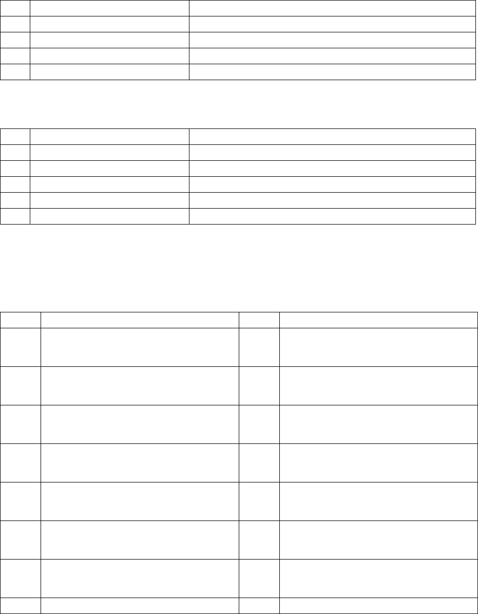
(1) Unplaced item list
No. Item displayed Contents
1 Compo. ID Unplaced component ID of the placement data
2 Ckt. Unplaced circuit pattern No.
3 Step Unplaced placement step
4 error Reason of unplacement
Descriptions of errors
(a) Approximate classification
No. Display Cause of the error
1 Mark recognition Unplaced because of failure of IC mark recognition
2 LA recognition Unplaced because of failure of component LA recognition
3 Component Unplaced because of component type errors
4 Feeder unit type Unplaced because of failure of feeder units
5 Setting Unplaced because of failure of setting such as setup
(b) Details
Details of errors are available for each error of approximate classification and
show the cause of each error, and they are displayed as follows:
① VCS recognition errors
Value Error contents Value Error contents
20 Bent lead 41 Ball outer frame recognition error (Bottom
side ball detecting error [Detection result:
less than 1/3])
21 Lead length error 42 Ball outer frame recognition error (Left side
ball detecting error [Detection result: less
than 1/3[]
22 Lead pitch error 43 Ball outer frame recognition error (Right side
ball detecting error [Detection result: less
than 1/3])
23 The number of detected leads is less than the
specified number.
44 Ball outer frame recognition error (Ball top
and bottom sides inclining error [three
degrees or more])
24 The number of detected leads is more than
the specified number.
45 Ball outer frame recognition error (Ball left
and right sides inclining error [three degrees
or more])
25 No lead is detected. 46 Ball outer frame recognition error (Distance
between the top side and the bottom side on
which balls are located is wide [half-pitch].)
26 The number of detected leads is one to three. 47 Ball outer frame recognition error (Distance
between the left side and the right side on
which balls are located is wide [half-pitch].)
27 Component frame detection error 60 All balls recognition error (Ball pitch error)