KE2010.Instruction Manual.Ver.2.01,Rev.08.pdf - 第445页
6 − 69 6.4.1.1 Set ting the number of components Aft er setting components on t he feeder units (tape f eeder , step f eeder, bulk f eeder, tray holder, MTC and/or MTS) specified on t he Pick dat a screen, set t he numbe…
6 − 68
④ Detailed information
Lead number, measurement result, X-coordinate, Y-coordinate, Z-coordinate,
coplanarity value and colinearity value are shown here.
• The lead numbers are assigned sequentially from “0”.
• The measurement result “1” indicates that an error was detected at the
lead.
• Coordinates are output in mm.
• The X-coordinate and Y-coordinate are relative coordinates viewed from
the center of a component.
• The Z-coordinate, coplanarity value and colinearity value indicate the
reference position viewed from the lead height. (If the lead height is
higher than the reference position, a negative value is output.)
Each item of the detailed information is output in order independent of the
measurement posture, and the bottom side, right side, top side and of the left
side of component data are output in this order.
If a coplanarity error occurs, only a coplanarity value is set but a colinearity
value is not set. If a colinearity error occurs, only a colinearity value is set.
A Z-coordinate is always output.
CAUTION
The head starts to move immediately after the "Retry" button is selected
or the "Skip" button is selected, and the <START> switch is pressed.
Then the machine restarts PWB production.
To avoid a risk of injury, do not place your hand in the machine, nor
move your face or head close to the machine during operation.
Before pressing the <START> switch, check that there is no one who is
working in the machine.
Before pressing the <START> switch check that there is no one who
can be injured when the head starts to move.
Before pressing the <START> switch, check that there are no obstacles
(tools and jigs) attached or left in the machine.
Even when "Stop production after ejecting PWB" is selected, X and Y
axes and the head continue to move to replace nozzles.
To avoid a risk of injury, do not place your hand in the machine, nor
move your face or head close to the machine even after stopping the
production.
6 − 69
6.4.1.1 Setting the number of components
After setting components on the feeder units (tape feeder, step feeder, bulk feeder,
tray holder, MTC and/or MTS) specified on the Pick data screen, set the number of
components to the main unit.
The system has the function for indicating that the number of remaining components
is less than the specified level by flashing the yellow signal light. If you set the
number of components, you can use this function.
If a component pick-up retry over error occurs at a feeder, holder, MTC or MTS, the
Production utility handles that feeder as a malfunctioning feeder and skips it to
continue the current production.
To resume the suspended production after adjusting the malfunctioning feeder so that
it can pick up a component, you have to clear the error with this number of component
setting function.
③ Descriptions of the buttons
No. Item Description
1 DTS change Replaces a tray of a DTS with another one. You cannot select this button if
any DTS component is not specified with the production program.
2 Replenish
Comp
Enters the value set in the “Initial” field into the “Remain” field of the line at
which the input focus is located, and clears all warnings.
3 Clear Enters the value set in the “Initial” field into the “Remain” field of the line at
which the input focus is located, and clears all warnings.
4 OK Validates the settings on the displayed “Parts no. setup” dialog box, quits this
dialog box, and then returns to the “Production conditions” or “Production
status” screen from which you invoked this dialog box.
5 Cancel Quits the displayed “Parts no. setup” dialog box without validating the settings
on this dialog box, and then returns to the “Production conditions” or
“Production status” screen from which you invoked this dialog box.
6 APPLY Validates the settings on the “Parts no. setup” dialog box.
④ How to set the number of the remaining components
When you click the right button of a trackball, you can set the following items by
selecting them from the displayed list.
No. Item Description
1 Replenish
Comp
Enters the value set in the “Initial” field into the “Remain” field of the line at
which the input focus is located, and clears all warnings.
2 Clear Enters the value set in the “Initial” field into the “Remain” field of the line at
which the input focus is located, and clears all warnings.
3 Replenish all
feeders
Executes the [Replenish Comp] command for all types of components.
4 Clear all Executes the [Clear] command for all types of components.
6 − 70
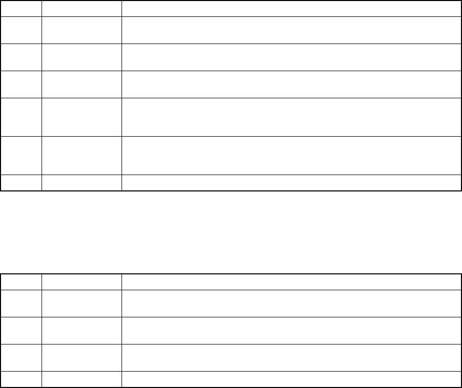
6.4.2 When an error occurs
When you check the check box “Stop system on any error.” displayed on the
“Production (Pause)” option setting screen, the system pauses if an error such as a
retry over error, LA recognition error and VCS error, which is to be displayed on the
Retry list, occurs.
Figure 6.4.2.1 Dialog box indicating that an error occurs
(Screen example when you use a KE-2020)
When you press the <START> switch, the system restarts production, and when you
press the <STOP> switch, the production stop dialog box appears on the screen, then
the system starts aborting the current production.
① Production Restart mode
Depending on your selection of the radio button displayed on the dialog box,
the system restart-operation to be performed when you press the <START>
switch varies as shown below:
Restart mode Operation to be performed when the system restarts production
Retry The system restarts production from the pick-up/placement cycle of the component which
caused an error.
Skip The system skips the pick-up/placement cycle of the component which caused an error, and
restarts production from the next pick-up cycle.
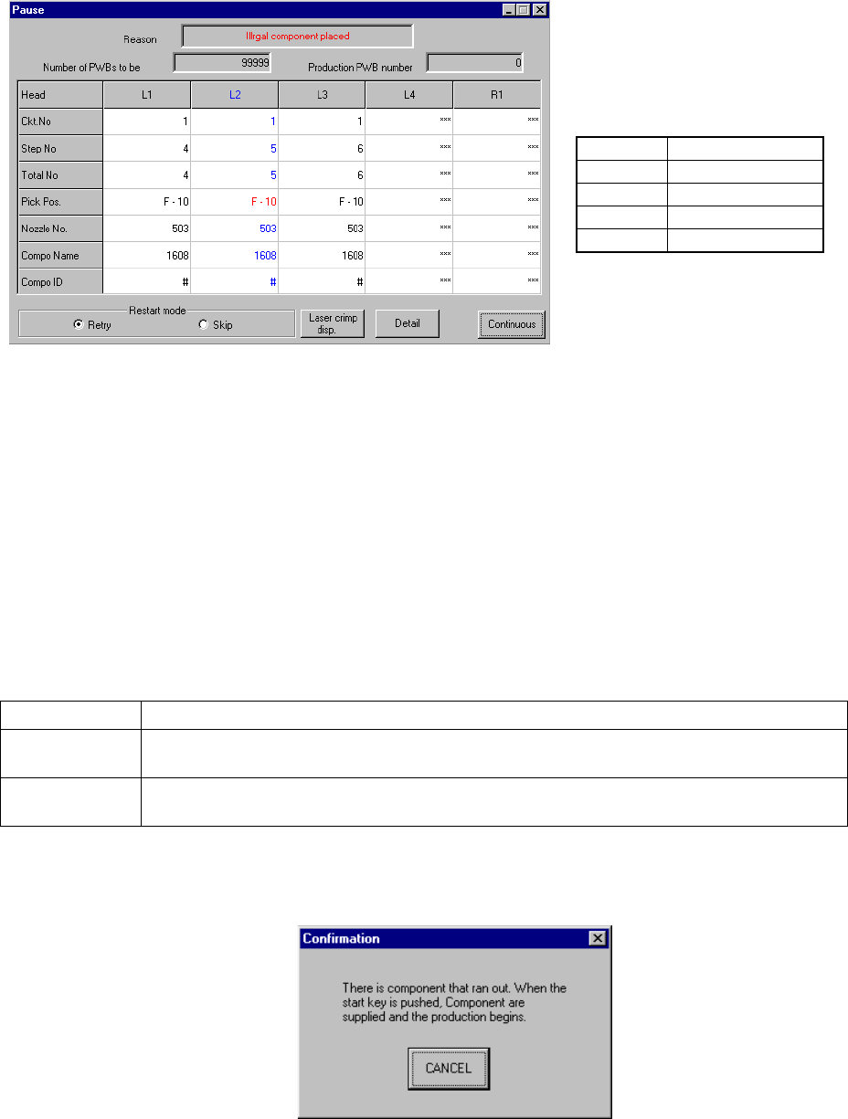
When you select “Retry”, the following message appears on the screen if the
stocked components run out at the feeder that caused an error.
• The actually displayed names
under the caption “Head” vary
depending on the model you use.
Model
Head name
KE-2010
L1 to L4
KE-2020
L1 to L4, R1
KE-2030
L1 to L4, R1 to R4
KE-2040
L1, R1