KE2010.Instruction Manual.Ver.2.01,Rev.08.pdf - 第460页
6 − 84 6.4.11 Check items at starting of production W hen y ou press the <ST ART> switch at star t of production, the system checks the following item s to decide if it can star t production. If the machine cannot …
6 − 83
When you select the “Execute” radio button and press the <Start> key, the system
starts tracking the placement result. Check to see if a component is already
placed on the next placement point of the last placement point.
When you select the “Not Execute” radio button and press the <Start> key, the
system starts the continuous production without tracking the placement result.
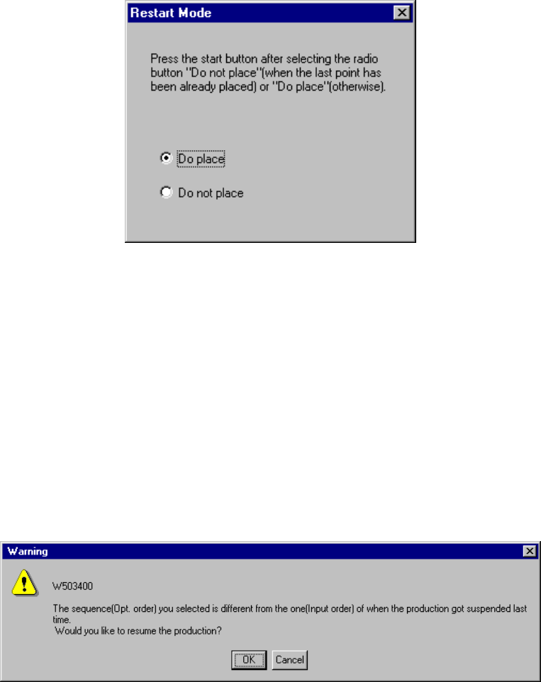
After tracking the placement result, the system displays the following dialog box.
Figure 6.4.10.5 Restart Mode dialog box
If a component is not placed on the tracked position, select the “Do place” radio
button. Otherwise, select the “Do not place” radio button. Then press the
<Start> key to start the continuous production.
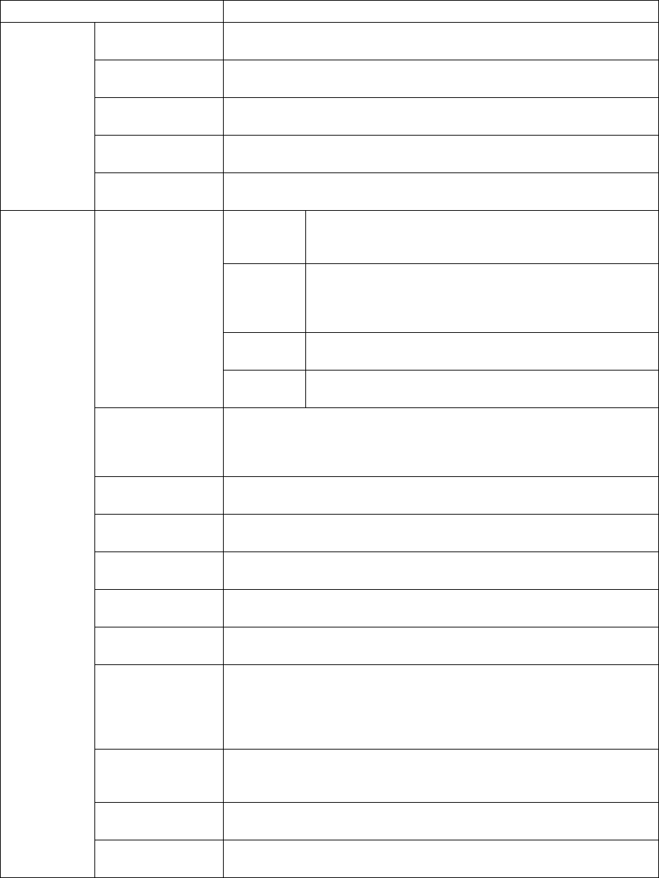
⑤ “Question” dialog box displayed when the continuous production starts
When you change the sequence (from “Input order” to “Opt. order”) on the PWB
production conditions dialog box and start the continuous production, the following
“Warning” appears on the screen.
6 − 84
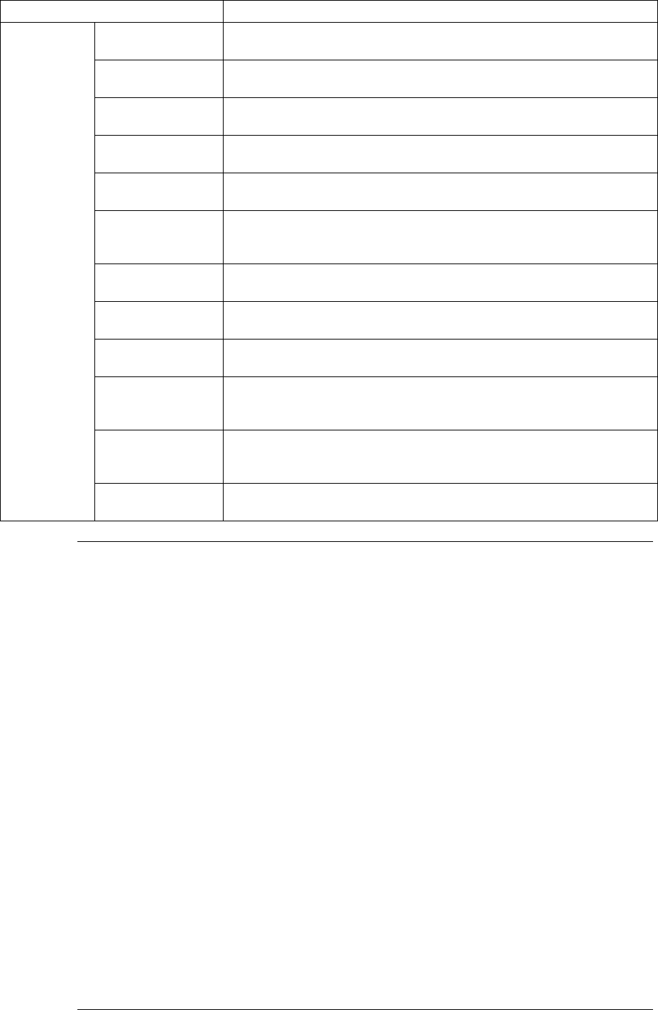
6.4.11 Check items at starting of production
When you press the <START> switch at start of production, the system checks the
following items to decide if it can start production. If the machine cannot start
production, an error occurs.
Check items Check contents
Origin setting If origin return is performed. Without origin return, normal operation is
impossible.
Servo If servo is set ON. With the servo set OFF, normal operation is
impossible.
Air If air pressure is too low. With insufficient air pressure, normal operation
is impossible.
Feeder bank If the feeder bank is lifted up. Components cannot be placed if the
feeder bank is moved down.
Hardware
Feeder floated If the feeder is installed correctly. The head may collide with the feeder if
operations started with the floated feeder.
PWB data Checking completeness of PWB data
Checking whether BOC mark recognition teaching is
completed
Placement
data
Checking completeness of placement data of each
placement point (except for those to be skipped)
Checking whether IC mark recognition teaching is
completed
Component
data
Checking completeness of component data to be referred
by placement data
Completed PWB
Pick data Checking completeness of pick data to be referred by
placement data
MS parameter
matching
Checking if the PWB reference side, PWB transport direction and PWB
positioning system set for the machine are the same as those set in PWB
data of a production program. If they are not the same as each another
respectively, the machine cannot place components on a board correctly.
Placement
coordinates
With the software limit, checking whether the head is located within its
movable area when the machine places components in input order.
Pick coordinates With the software limit, checking whether the head is located within its
movable area when the machine places components in input order.
Offset of automatic
calculation
Checking the pick coordinates: if they have been changed to outside the
specified limit range with respect to the result of automatic calculation.
Match of the circuit
assignment (angle)
Checking whether the rotation angle of the non-matrix PWB is 90, 180,
270, or 360 degrees if the BOC mark type is circle, eclipse, or not-binary.
Compo
abandonment
Checking the Compo abandonment selection (specified as Component
data) and the usage of the IC collection belt.
Number of nozzles Check to see if all of the nozzles necessary for production are installed.
For optimization order production, if the number of nozzles actually
installed is different from that of the nozzles to be used, the machine is not
in the optimized state. To do check this state, the machine checks the
number of nozzles installed.
Head Checks to see if the head is used or not used. If you are to place a
component with a unused head, or if all heads are set as unused, the
machine cannot place a component properly.
OCC2 If the OCC2 camera is set as unused, the machine cannot recognize a
mark or feeder bank.
Production
program
Bad mark sensor Checks to see if you are to detect a bad mark although the bad mark
sensor is set “unused”.
6 − 85
Check items Check contents
Shape reference Check to see if you select “Shape reference” as PWB data although the
shape reference function is set “unused”.
IC conveyor belt Checks to see if you select “IC conveyor belt” for component
abandonment although the IC conveyor belt is set “unused”.
Coplanarity Checks to see if you are to perform the coplanarity check although the
Coplanarity option is set “unused”.
Tombstone
detection
Checks to see if there is any component which is set to be
Tombstone-checked although “Tombstone detection” is not selected.
Template matching Checks to see if there is any mark which uses the user-defined template
although the template matching function is not selected.
Different type of
component
detection
Checks to see if there is any component whose dimension is to be
checked although the Dimension check function is not selected.
Standard VCS Checks to see if there is any component which is set to be recognized
with the standard VCS although the standard VCS is set “unused”.
Option VCS Checks to see if there is any component which is set to be recognized
with the optional VCS although the optional VCS is set “unused”.
Multi-view
recognition
Checks to see if there is any component whose multi-view is set to be
recognized although the Multi-view recognition function is not selected.
BGA all ball
recognition (for
standard VCS)
Checks to see if there is any BGA component whose balls are all to be
recognized (including the user-defined pattern) although the “All balls” is
not selected as the recognition type(for the standard VCS).
BGA all ball
recognition (for
option VCS)
Checks to see if there is any BGA component whose balls are all to be
recognized (including the user-defined pattern) although the “All balls” is
not selected as the recognition type(for the optional VCS).
Production
program
Supply device Check to see if there is any component for which all supply units are set
as “unused”.
Notes: 1. The machine checks the feeder bank only if a feeder bank is checked
on the "Device enable" menu invoked from the Machine Setup menu.
2. For coordinate check, a fault can be regarded as "Warning" and
production can be forcibly started. In this case, however, an operation
error of shaft driver may occur during production.
3. "Warning" of coordinate range check is to be referred by input order
placement of optimized production program.
The same check is performed for editing of production program and for
optimization. So, this item is to be ignored when production is
performed with the data not optimized or when optimization production
is performed.
4. If the actual pick coordinates largely differ from the automatically
calculated pick coordinates, a non-standard feeder may be installed or
correct pickup may be impossible because the incorrect mounting hole
was specified in Pick data. To prevent such a mistake from occurring,
the difference between the actual pick-up coordinates and the pick-up
coordinates automatically calculated is checked. However, when a
non-standard feeder (stick feeder in particular) is used, warning can be
ignored and production can be started although the warning is
displayed on the screen.
5. The corresponding message appears on the screen if an error occurs
during hardware check.