KE2010.Instruction Manual.Ver.2.01,Rev.08.pdf - 第48页
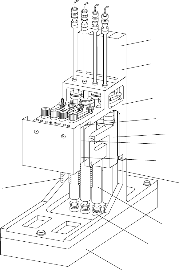
1 − 31 1.2.4 Head- related unit: parts identification Figure 1.2.4.1 Head-rel ated unit (MNLA head) ① Nozzle outer ⑦ θ -axis encoder ② Laser alignm ent sensor ⑧ Ball screw ③ Z-ax is motor ⑨ Linear way ④ Z-axis encoder ⑩ …
1 − 30
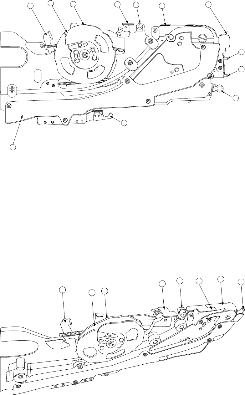
FF05/08 Parts identification (2/2)
12
11
16
17
4
5
15
13
7
2
1
10
Figure 1.2.3.6 Detailed illustration of the right side
① X axis reference pin A ⑧ Stopper
⑮ Guide cover
② X axis reference pin B ⑨ Free link
⑯ Unreeling plate
③ Sprocket wheel ⑩ Tape holder
⑰ Unreeling guide roller
④ Upper cover ⑪ Cover tape fixing plate
⑱ Reel support
⑤ Upper cover hook ⑫ Lock release lever
⑲ Tape groove
⑥ Shutter ⑬ Lock holder
⑦ Knock lever ⑭ Tape guide
12
11
10
16
17
5
6
4
Figure 1.2.3.7 Detailed illustration of the top side
1 − 31
1.2.4 Head-related unit: parts identification
Figure 1.2.4.1 Head-related unit (MNLA head)
①
Nozzle outer
⑦
θ-axis encoder
②
Laser alignment sensor
⑧
Ball screw
③
Z-axis motor
⑨
Linear way
④
Z-axis encoder
⑩
Head-up spring
⑤
Z slide shaft
⑪
Head top bracket
⑥
θ-axis motor
⑫
Z slide bracket
②
①
⑤
⑨
④
③
⑧
⑪
⑦
⑥
⑩
⑫
1 − 32
(1) Main body of head
The head unit consists of the laser align sensor used to detect placement and
angle offsets of the component, and the Z slide shaft which can be moved up and
down, or be turned.
The Z slide shaft and the Z slide bracket of the Z axis are driven with rotations of
the ball screw.
The θ-axis encoder located on the upper section of the θ-axis motor detects the
angle of a component.
The machine is equipped with one units as standard parts.