KE2010.Instruction Manual.Ver.2.01,Rev.08.pdf - 第488页
6 − 1 12 − − − − Requirements for resuming and axes ret urning To display the “O riginating ” dialog box, all axes should have been returned to their home positions respect ively at least once. − I f an asynchronous even…
6 − 111
6.4.15 Resuming and Returning All Axes to Their Home Positions
6.4.15.1 Normal Axes-Returning
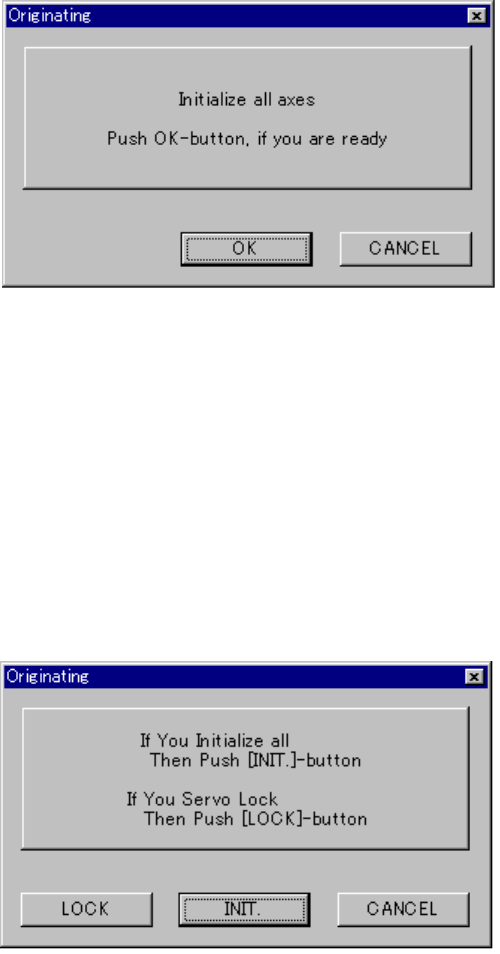
If you press the <ORIGIN> key when the system starts up or when the system cannot
resume and return all axes to their home positions, the following “Originating” dialog
box appears on the screen.
Figure 6.4.15.1 Normal axes-returning dialog box
• <OK> button: returns all axes to their home positions respectively.
• <CANCEL> button: quits the “ORIGINATING” dialog box.
6.4.15.2 Resuming and axes returning
If you press the <ORIGIN> key when the system can return all axes to their home
positions respectively, the following “ORIGINATING” dialog box appears on the
screen.
Figure 6.4.15.2 Resuming and axes-returning dialog box
• <LOCK> button: locks the servo of each axis and moves the PWB transport
support plate to its waiting position.
• <INIT.> button: returns all axes to their home positions respectively.
• <CANCEL> button: quits the “Originating” dialog box.

6 − 112
−
−−
− Requirements for resuming and axes returning
To display the “Originating” dialog box, all axes should have been returned to their
home positions respectively at least once.
− If an asynchronous event occurs that turns off the servo power supply, whether
the system can resume and return all axes to their home positions is described on
the table below.
Table 6.4.15.1
No. Asynchronous event
Whether the system can resume
and return all axes
1 The main unit stops due to emergency. ×
2
The system stops for a second because it
detects a feeder float error.
○
3 Each axis limit sensor is activated. ×
4
The MTC stops due to emergency.
×
5
The MTS stops due to emergency.
×
6
Each axis alarm is output.
×
7 The system stops due to emergency to
prevent heads from interfering each other.
×
8 The area sensor is activated. ○
9 Power off (for a CE machine only) ○
−
If either of the following events occurs, the system cannot resume and
return all axes to their home positions.
The system tried to return all axes to their home positions respectively,
but could not.
The system tried to resume and return all axes to their home positions,
but could not completely.

6 − 113
6.5 Trial Run
When you select the [Production conditions] command from the menu bar, then the
[Trial Run] command on the displayed menu, the "Trial Run conditions" screen
appears.
CAUTION
The "Trial run" starts immediately after the <START> switch is pressed.
To avoid a risk of injury, do not place your hand in the machine, nor
move your face or head close to the machine during operation.
Before pressing the <START> switch, check that there is no one who is
working in the machine.
Before pressing the <START> switch, check that there is no one who
can be injured when the head starts to move.
Before pressing the <START> switch, check that there are no obstacles
(tools and jigs) attached or left in the machine.
(1) Setting items
No. Item Description
1 Setting items
selection
Switch the displayed dialog box among the "Production conditions" dialog box,
"Trial run conditions" dialog box, and the "Dry run conditions" dialog box.
2 Trial PWB no. Set the number of boards for trial run.
3 Trial ckt. Set the circuit for trial run. This is not used for single circuit boards. The
following setting can be made.
All ckt.: Components set for trial run are placed for all circuits.
Ref. ckt.: Components set for trial run are placed for reference circuits only.
4 Trial range Set the range for trial run. The following setting can be made.
Spec. place: Only for the placement positions set as Yes for the “trial” field of
the placement data.
Spec cmpnt: Only for the components set as Yes for the “trial” field of the
component data.
All: For all placement positions.
5 Tracking Station Select the unit to be tracked: left, right or both.
6 Placement ofs. Designate offset for all placement positions. This offset is added to the
placement positions for
actual component placement. (Range: ±2.0 mm)
7 Place tracking After trial run of the board, designate whether or not to perform placement
tracking by the camera. If performed, set whether it is manual or automatic.
Off: Placement tracking is not performed.
Automatic: Placement tracking is performed automatically.
Manual: Stops at each placement position, and then goes to the next
placement position through a key-in by the operator.
8 Pick tracking Before trial run of the board, designate whether or not to perform pickup position
tracking by the camera. If performed, set whether it is manual or automatic.
Off: Pickup tracking is not performed.
Automatic: Pickup tracking is performed automatically.
Manual: Stops at each pickup position, and then goes to the next pickup
position through a key-in by the operator.
9 Automatic interval When tracking is performed automatically, designate the stop time duration at a
stop position. (Unit is in 10 ms, and 1 is equivalent to 10 ms.)