KE2010.Instruction Manual.Ver.2.01,Rev.08.pdf - 第514页
6 − 138 6.7.2.5 Laser hei ght check operation 6.7.2.5. 1 Operation tr ansition duri ng laser height check Displayed screens and state are chang ed during laser height check as shown below: PREV/NEXT User oper ation MEAS.…
6 − 137
② Returning a component after check
After checking laser height, the system returns some components onto their
original positions and discards other ones depending on their packaging style
as shown in Table below. When the setting item “Compo Reject to”, indicating
the component discarding method, is set to “Trash conveyor” or “Protect”, the
system discards a component according to this setting. The system discards a
component on a position which is set with the "Compo abandonment" selection
of Component data. For a component whose size is 1 mm or less, it may be
placed on its side or be turned upside down when it is returned onto the original
position. Therefore, the system asks you how to handle it.
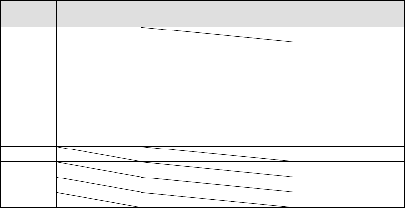
Table 6.7.2.4 Conditions for returning/discarding a component
Packaging
style
Condition 1 Condition 2 When
returning
When
discarding
32-mm tape feeder
○
Components whose shorter side is 1
mm or less
Inquiry *1
Tape
Tape feeders other
than the above
Components whose shorter side is 1
mm or more
○
○
*2
Components whose shorter side is 1
mm or less
Bulk
Components whose shorter side is 1
mm or more
○
○
*2
Holder
○
○
*2
MTC
○
○
*2
MTS
○
○
*2
Stick
○
*1 The system displays the dialog box which asks you whether to return a
component or discard it. In Continuous measurement mode, the system
displays this dialog box before starting measurement operation.
*2 The system discards a component when the setting item “Compo Reject to”
is set to “Trash conveyor” or “Protect”.
③ Selecting a feeder used to pick a component
If two or more feeders are assigned to the same type of components in Pick
data, the system, as the default setting, starts picking up components from one
whose data was entered first of all. Only in Single check mode, you can
change the feeder intentionally.
④ Changing the coordinates of a pick-up position
When a component is not picked up properly, manually enter the coordinates or
use the HOD device to teach them to change the coordinates of a pick-up
position.
⑤ Manual component pick-up
If there is no Pick data created, you can manually attach a component to the
nozzle. However, in this case, you cannot enter coordinates that indicate the
component pick-up position. You cannot operate a feeder either.
6 − 138
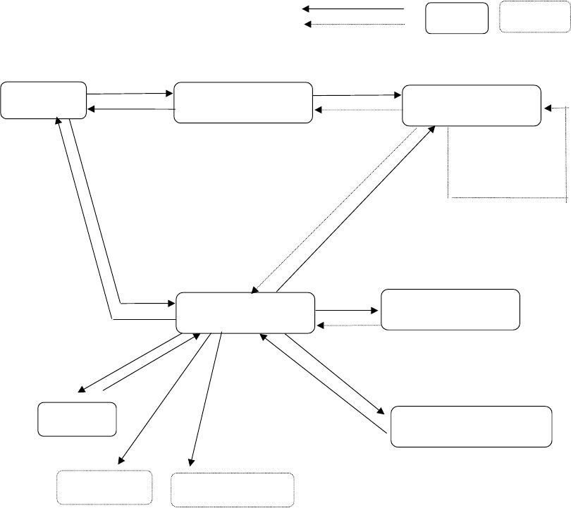
6.7.2.5 Laser height check operation
6.7.2.5.1 Operation transition during laser height check
Displayed screens and state are changed during laser height check as shown
below:
PREV/NEXT
User operation
MEAS.
START
ENTER/CANCEL
Process
Dialog box Process only
Selection
"Continuous inspection"
dialog box
Laser check
BACK
A
ll components
finish being
checked.
"Inspection" dialog box
Normally
BACK (only in Continuous
check mode)
Error
Change/laser
BACK
"Inspection" dialog box for
setting the conditions
"Inspection" dialog box
displayed in Single check
mode
Single check
Success/error
INSP.
"Laser position
measurement" dialog box
BACK
Change of a component
pick-up position
Feeder knock
FEED
Teaching
HOD device key
6 − 139
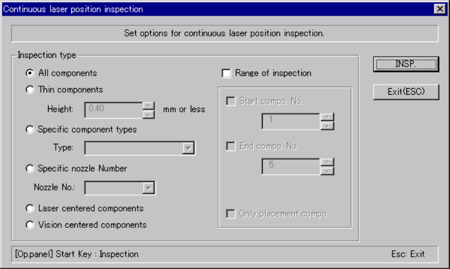
6.7.2.5.2 Continuous laser position inspection
• When you select the [Laser check] command on the [Check] menu invoked
from the [Tool] menu, the "Continuation inspection" dialog box appears on the
screen.
• Set the "Component of meas." and "Bounds of meas." menu items on the
"Continuation inspection" dialog box.
• When you click the <INSP.> button or press the <START> switch on the
"Continuation inspection" dialog box, the system starts checking the laser
height within the range specified.
• When the system centers a component successfully, the result of the check
operation is displayed on the "Inspection" screen, but the system does not
pause temporarily.
• The system repeats a check of a component until it finishes checking the last
component within the specified range, then returns to the "Continuation
inspection" dialog box.
• If the system detects an error during check, it enters Single check mode.
(1) "Continuous laser position inspection" dialog box
When you select the [Check] command on the [Tool] menu, then the [Laser
check] command, the following "Continuation inspection" dialog box, which
allows you to set the conditions for checking components continuously,
appears on the screen.
Figure 6.7.2.5.2.1 "Continuation inspection" dialog box