KE2010.Instruction Manual.Ver.2.01,Rev.08.pdf - 第524页
6 − 148 6) Short- cut k eys On the "I nspection" screen, the f ollowing short-cut k eys are provided. Key board Operation panel HOD key Action F10 ENTER Performs a "independent inspection”. F9 Cancel…
6 − 147
3) <MEAS.> button
This button measures the laser height.
(See Section 6.7.2.5.4 "Measuring laser height".)
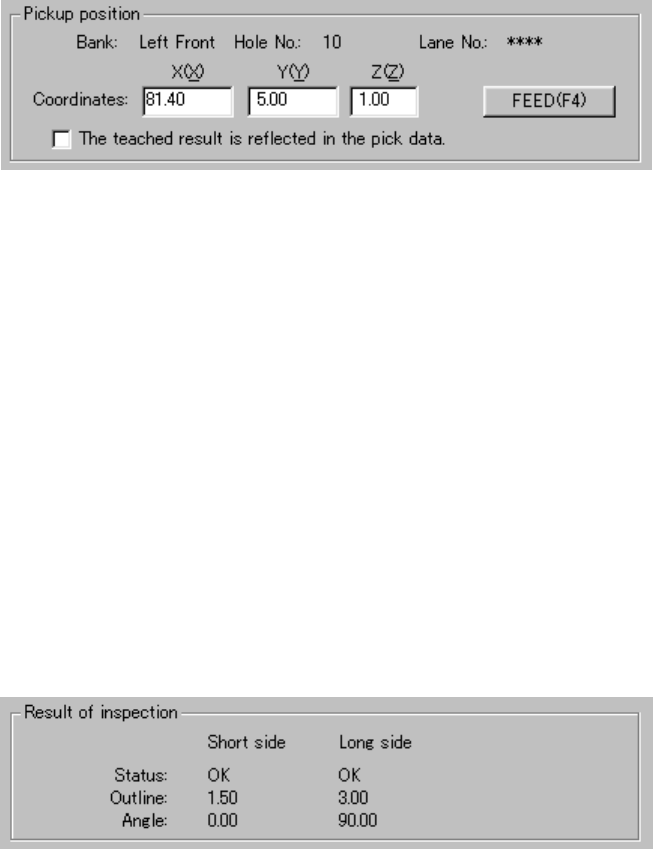
4) Pickup position
The pick-up position of a component is displayed here. You can change
the pick-up position to the previous alternative component or next one.
① <FEED> button
This button knocks a feeder (other than a 32-mm paper tape feeder)
once to feed a component.
② "The taught results reflected in the pick data."
Check this check box if you want to store the result taught by the
HOD device into Pick data. When unchecked, only the coordinates
of the current pick-up position are applied to Pick data.
5) Result of inspection
After checking laser height, the result is displayed in this "Result of
inspection" column. The "Short side" and the "Log side" indicate the data
obtained when the system detects the minimum width of a component for
the first time and second time respectively. These values are effective
only when each status of the "Short side" and "Long side" is "OK".
① Status
OK: Centering is done successfully.
Number: Centering failed. (Each number indicates the error code
number of the laser status.)
② Outline
The width of a component which is detected with laser when the
component is centered successfully is displayed here.
③ Angle
The angle obtained when a component is centered is displayed here.
6 − 148
6) Short-cut keys
On the "Inspection" screen, the following short-cut keys are provided.
Keyboard Operation panel HOD key Action
F10 ENTER Performs a "independent inspection”.
F9 Cancels an “independent inspection”.
F7 Measures the checked value.
F4 Knocks a feeder.
F5 PREVIOUS Previous alternative component.
F6 NEXT Next alternative component.
ESC CANCEL Returns to the previous screen.
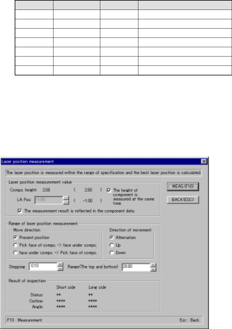
6.7.2.5.4 Measuring laser height
(1) Measuring laser height
When you select the <MEAS.> button on the “Inspection” screen, a screen
shown below appears:
“Laser position measurement” dialog box
6 − 149
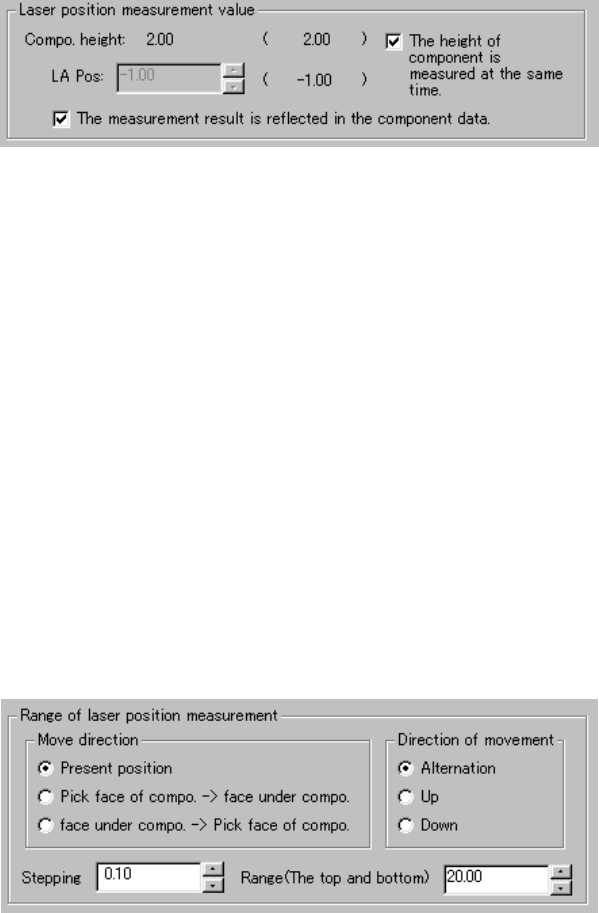
(1) Laser position measurement value
The descriptions required to measure laser height are displayed here.
Values set before measurement are displayed in parentheses.
① LA Pos (laser position)
You can change the laser height (position) as you like. The value
specified here is used as the current laser height when the system
starts judging if the laser height is within the appropriate range.
② "The height of component is measured at the same time."
When checked, the system measures the height of a component
before measuring the laser height. It automatically calculates the
laser height also at the same time. In this case, the laser height
automatically calculated is used as the current laser height when the
system judges if it is within the appropriate range. Therefore, you
cannot specify the laser height.
③ "The measurement result is reflected in the component data."
Check this check box if you want to store the measured laser height
into Component data immediately.
2) Range of laser position measurement
① Direction of movement
The system repetitively measures the laser height from the height
displayed in the "Laser position measurement value" column within
the range specified. When a component is centered with laser
successfully, the system finishes measuring the laser height.
Select one of the radio buttons below.
1) Alternation
2) Up
3) Down