KE2010.Instruction Manual.Ver.2.01,Rev.08.pdf - 第527页
6 − 151 6.7.3 SOT Direction Check 6.7.3.1 O verview The machine uses t he OCC to check the 3-t ermianl SO T direct ion. 6.7.3.2 Checki ng funct ion The f unction of this 3-t erminal SOT direction check is overviewed in T…
6 − 150
Enter the distance to be moved in units of step and the up and down
range in each edit box.
部品側面
移動範囲
移動ステップ
現在レーザー高さ
移動範囲
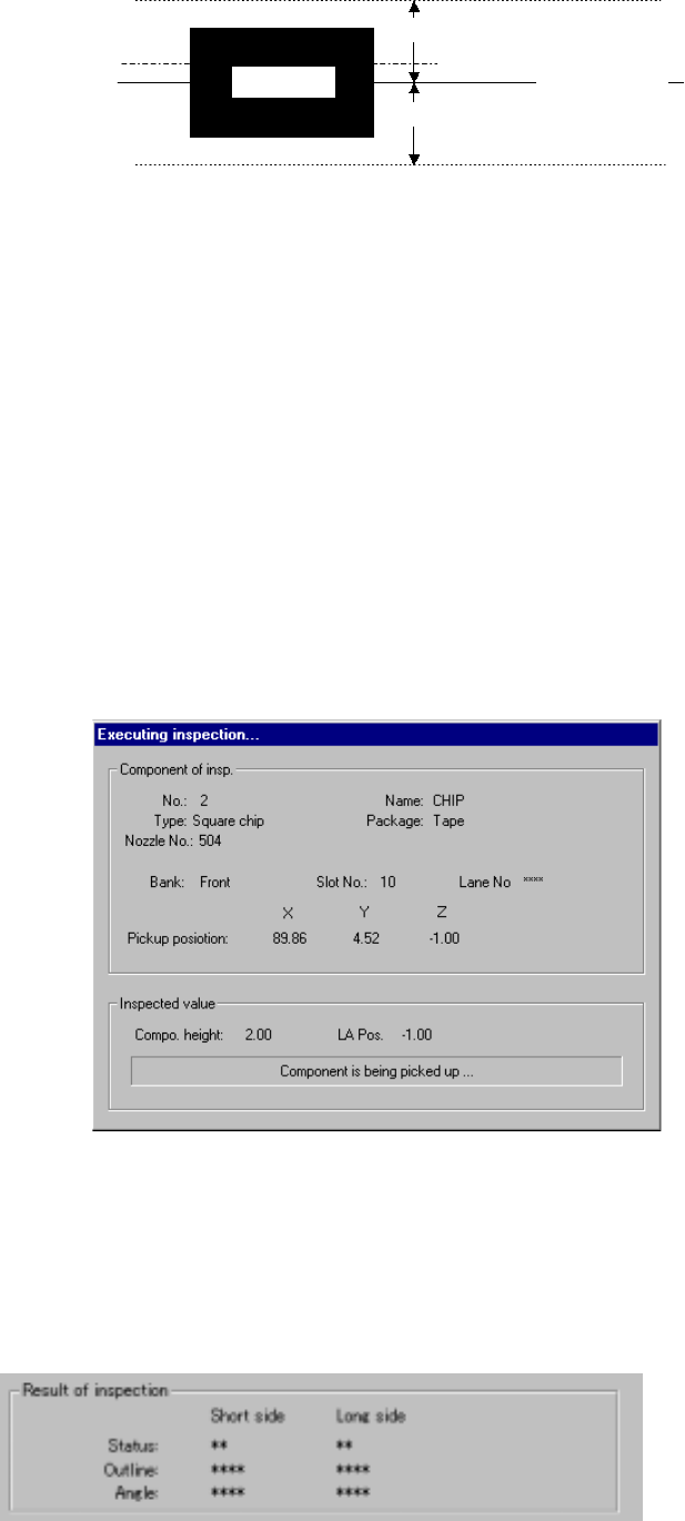
Figure 6.7.2.5.4 Laser height judgment range (current height)
② Pick face of compo. → face under compo.
③ face under compo. → Pick face of compo.
The system measures the component height within the range
specified here in addition to a value displayed in the "Range of laser
position measurement". The start point can be on either the
picked-up side or bottom side of a component.
3) Screen displayed while the system is inspecting the laser height in Single
check mode
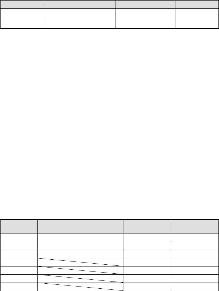
The following dialog box appears on the screen while the system is
inspecting the laser height in Single check mode. Data on a component
being inspected, pick-up position and laser height are displayed on this
dialog box to show the current inspection progress.
Figure 7.7.2.5.4.3 “Executing inspection” dialog box
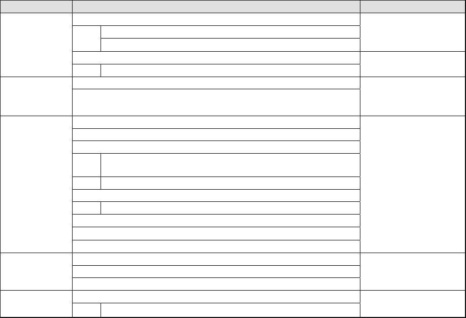
4) Result of inspection
The laser status value appears here if a component is centered with laser
successfully. The meaning of each item is the same as that for check
operation.
Side of a
component
Movement range
Movement range
Movement step
Current laser
height
6 − 151
6.7.3 SOT Direction Check
6.7.3.1 Overview
The machine uses the OCC to check the 3-termianl SOT direction.
6.7.3.2 Checking function
The function of this 3-terminal SOT direction check is overviewed in Table 6.7.3.2.1.
Table 6.7.3.2.1 SOT direction check function
Check Description Check mode Remarks
3-terminal SOT
direction check
Checks to see if the direction
of a 3-terminal SOT
component is correct.
Independent inspection
Continuous inspection
6.7.3.3 Operations
① Head used to pick up a component
The system automatically selects a head that is used to pick up a component.
The system selects and uses a nozzle already attached on a head rather than
one not attached so that the frequency of nozzle replacement can be reduced.
However, the system may use a different head every time it measures a
component depending on the nozzle attachment condition.
② Applicable component size
The applicable SOT component size is 1608 to 4.0 mm x 4.0 mm. The width
and length of an electrode is 0.2 mm to 1.0 mm and 0.1 mm to 1.0 mm
respectively.
③ Returning a component after checking it
The system returns some checked components onto their original positions, or
discards other ones depending on their packaging style as shown in Table
below. The “Question” dialog box appears on the screen to prompt you to
select whether to discard a checked component. Where to discard a
component is determined according to the setting of “Compo Reject to” on the
Component data screen. When checking continuously, the system displays
the selection dialog box that asks you if it discards all components before start
of check, or displays the “Question” dialog box every time it checks a
component.
Table 6.7.3.3.1 Requirements for returning/discarding a component
Packaging
style
Requirements When returning a
component
When discarding
a component
32-mm tape feeder
○
Tape
Tape feeders other than the above
○
○
*1
Bulk ○ ○ *1
Holder ○ ○ *1
MTC ○ ○ *1
MTS ○ ○ *1
Stick ○
*1 The system discards a checked component when the menu item “Compo Reject
6 − 152
to” is set to “Trash conveyor” or “Protect”.
③
Selecting a feeder used to pick a component
If two or more feeders are assigned to the same type of components on the
Pick data screen, the system starts picking up components from one whose
data was entered first of all by default. Only in Independent Inspection mode,
you can change the feeder used to pick up a component intentionally.
④
Changing the coordinates of a component pick-up position
When a component is not picked up properly, manually enter the coordinates or
use the HOD device to teach them to change the coordinates of a component
pick-up position.
⑤
Manual component pick-up
If there is no Pick data created, you can manually attach a component to a
nozzle. However, in such a case, you cannot enter coordinates that indicate
the component pick-up position. You cannot operate a feeder either.
⑥
Check
The system places a picked-up component onto the SOT direction check stage
at a 0-degree angle, and uses the left OCC to judge if this angle is appropriate
or not.
6.7.3.4 Operation sequence
6.7.3.4.1 Independent inspection sequence
The SOT independent inspection function is described below.
Table 6.7.3.4.1 SOT direction independent inspection
Operation Remarks
1. Check to see if an SOT direction inspection is available or not.
Checks to see if the specified feeder is available or not..
Checks to see if a production program is created completely or not
Displays an error when
a check error occurs.
2. Initialization
Start of an
independent
inspection
Initializes a driver and other devices.
1. Selects a component to be checked.
Selection of a
component
2. Displays the component information.
Displays a dialog box or
an error if there is no
component to be
checked.
1. Displays the component information.
2. Displays a component pick-up position.
3. Makes a trivial adjustment of a component pick-up position.
Makes a trivial adjustment of a component pick-up position by
teaching or manual input of data.
Checks to see if the adjusted value is stored onto Pick data or not.
4. Selects a component to be picked up.
Changes a feeder to the alternate feeder.
5. Controls a knocking operation of a feeder.
6. Displays a check result.
Execution of an
inspection
7. Checks the direction of an SOT component.
Displays a dialog box.
1. Controls picking-up of a component.
2. Controls execution of the SOT direction inspection.
Check of the
SOT direction
3. Controls returning of a component.
1. Quit process
End of an
independent
inspection
Finishes operating a driver or other devices.
The independent inspection sequence is shown in Figure 6.7.3.4.1.